Hello Guys,
I was pointed towards this forum from Reddit. I have purchased a Commodore PET 2001-16. Sadly it is not fully working.
I have taken it apart and i see tons of modifications, like jumper cables running on the back of the board. I dont think i have a way to actually find out what these fixes do, so I think my best course of action is to reverse all the "fixes" and start the trouble shooting from there. Then, actually fix it instead of running these jumper cables. Is this the correct course of action?
I dont really have any experience with these sorts of computers but i saw one close by selling online for 200$ so i bought it. And now i will repair it and make it work again.
i am very open to buying modern parts Like these http://www.dasarodesigns.com/product/mp ... 3-version/ as long as they dont permanently stop me from making it original as possible if i by chance find original parts.
https://imgur.com/a/dqFy3in These are the pictures my machine and a short video of the issue im experiencing.
Thanks a million for any input, im really just worried about starting out with no real plan.
edit: im gonna add pictures of the back of the board later, where the jumper wires are run.
Bought a PET - Not working ^^
-
Commodore_PET
- Posts: 31
- Joined: 19 May 2020
- Location: Basel-Stadt, Switzerland
Bought a PET - Not working ^^
- Attachments
-
- The device itself
-
- A picture of a modification
-
- A picture of two of the modifications
-
- A picture of the Board inside the machine. The yellow sticker noted TYPE: CBM 3032
Last edited by Commodore_PET on Thu May 21, 2020 6:34 am, edited 2 times in total.
-
GARTHWILSON

- Forum Moderator
- Posts: 8773
- Joined: 30 Aug 2002
- Location: Southern California
- Contact:
Re: Bought a PET - Not working ^^
Welcome!
Mike Naberezny probably knows more about PETs than the rest of us, so hopefully he will jump it. I would definitely not go removing jumpers right away though. In many cases, products were sold that way brand new, rather than the manufacturer taking the long delays and high costs of re-doing a board after a problem showed up or a part became unavailable and they had to adapt to a different one.
Commodore_PET wrote:
Hello Guys,
I was pointed towards this forum from Reddit. I have purchased a Commodore PET 2001-16. Sadly it is not fully working.
I have taken it apart and i see tons of modifications, like jumper cables running on the back of the board. I dont think i have a way to actually find out what these fixes do, so I think my best course of action is to reverse all the "fixes" and start the trouble shooting from there. Then, actually fix it instead of running these jumper cables. Is this the correct course of action?
Mike Naberezny probably knows more about PETs than the rest of us, so hopefully he will jump it. I would definitely not go removing jumpers right away though. In many cases, products were sold that way brand new, rather than the manufacturer taking the long delays and high costs of re-doing a board after a problem showed up or a part became unavailable and they had to adapt to a different one.
http://WilsonMinesCo.com/ lots of 6502 resources
The "second front page" is http://wilsonminesco.com/links.html .
What's an additional VIA among friends, anyhow?
The "second front page" is http://wilsonminesco.com/links.html .
What's an additional VIA among friends, anyhow?

Re: Bought a PET - Not working ^^
Welcome indeed! You'll find quite a lot of repairs and diagnostics going on over on Dave Curran's site:
http://blog.tynemouthsoftware.co.uk/search/label/Pet
http://blog.tynemouthsoftware.co.uk/search/label/Pet
-
Commodore_PET
- Posts: 31
- Joined: 19 May 2020
- Location: Basel-Stadt, Switzerland
Re: Bought a PET - Not working ^^
GARTHWILSON wrote:
I would definitely not go removing jumpers right away though. In many cases, products were sold that way brand new, rather than the manufacturer taking the long delays and high costs of re-doing a board after a problem showed up or a part became unavailable and they had to adapt to a different one.
-
BigDumbDinosaur

- Posts: 9425
- Joined: 28 May 2009
- Location: Midwestern USA (JB Pritzker’s dystopia)
- Contact:
Re: Bought a PET - Not working ^^
Commodore_PET wrote:
I have purchased a Commodore PET 2001-16. Sadly it is not fully working.
Secondly, you can attach images to your posts here.
Thirdly, some of those patches look like they may have been done when the machine was manufactured. As Garth noted, that is not-uncommon, especially on machines of your PET's vintage. I would not disturb any of them at this time.
All-in-one units such as the PET can fail to operate due to a fault in the computer part of the circuit, a fault in the video circuitry or a failed CRT. A logic probe can assist in determining if you've got microprocessor activity going on and if appropriate control and bus signals are being generated.
Are you seeing any signs of a raster on the screen?
x86? We ain't got no x86. We don't NEED no stinking x86!
-
Commodore_PET
- Posts: 31
- Joined: 19 May 2020
- Location: Basel-Stadt, Switzerland
Re: Bought a PET - Not working ^^
BigDumbDinosaur wrote:
Firstly, welcome.
Secondly, you can attach images to your posts here.
Are you seeing any signs of a raster on the screen?
Secondly, you can attach images to your posts here.
Are you seeing any signs of a raster on the screen?
If i turn up the brightness setting on the back, i think see rastering. I see faint horizontal lines/bars and i think someone referred to this as rastering in a youtube video I watched.
-
BigDumbDinosaur
- Posts: 9425
- Joined: 28 May 2009
- Location: Midwestern USA (JB Pritzker’s dystopia)
- Contact:
Re: Bought a PET - Not working ^^
Commodore_PET wrote:
If i turn up the brightness setting on the back, i think see rastering. I see faint horizontal lines/bars and i think someone referred to this as rastering in a youtube video I watched.
Last edited by BigDumbDinosaur on Thu May 21, 2020 7:03 pm, edited 1 time in total.
x86? We ain't got no x86. We don't NEED no stinking x86!
-
Commodore_PET
- Posts: 31
- Joined: 19 May 2020
- Location: Basel-Stadt, Switzerland
Re: Bought a PET - Not working ^^
Hi again, im posting a picture of the screen brightness turned all the way up.
im also posting a picture of the back side wires, plus an other wire jumper on what i presume are the RAM chips.
im happy to provide any sort of pictures that will help trouble shooting.
In the original link I shared to pictures, ive added a bunch more
Thank you for the warm welcome!
im also posting a picture of the back side wires, plus an other wire jumper on what i presume are the RAM chips.
im happy to provide any sort of pictures that will help trouble shooting.
In the original link I shared to pictures, ive added a bunch more
Thank you for the warm welcome!
- Attachments
-
- This is a more complete view of the back with the cables, but they do seem to be factory made as the soldering looks identical to the other ones.
-
- This is the image of the back side of the RAM chips with some questioning soldering and a wire run between two.
-
- This is what i see when i turn up the brightness to max.
Re: Bought a PET - Not working ^^
To my amateur eyes, that screen looks correct for drawing a blank screen.
Time to check the computer side of things, is the clock working, is the CPU stuck in reset, do the address/data lines look good, that type of thing.
The main board bodge wires look like factory fixes, or are VERY well done repairs.
The RAM chips look like someone has attempted to reflow all of the chips and not cleaned up their flux. The bodge wires look fine, but someone thought the RMA was the issue and didn't do the neatest job with resoldering all of the chips.
Edit: Looking at the first post, someone socketed all of the RAM chips rather than reflowed, but it's still a messy job.
-
BigDumbDinosaur
- Posts: 9425
- Joined: 28 May 2009
- Location: Midwestern USA (JB Pritzker’s dystopia)
- Contact:
Re: Bought a PET - Not working ^^
Commodore_PET wrote:
Hi again, im posting a picture of the screen brightness turned all the way up.
im also posting a picture of the back side wires, plus an other wire jumper on what i presume are the RAM chips.
im also posting a picture of the back side wires, plus an other wire jumper on what i presume are the RAM chips.
The raster is pretty dim and the vertical sweep rate appears to be out of sync. Do you know if this is a PAL or NTSC PET?
Meanwhile, you or someone who is skilled in the art needs to start poking around with a logic probe to see if the 6502 is alive. A check needs to be made for an input clock and that the 6502 is generating clock at its two outputs. I would make those checks before anything else. If there is no clock nothing will work.
x86? We ain't got no x86. We don't NEED no stinking x86!
-
Commodore_PET
- Posts: 31
- Joined: 19 May 2020
- Location: Basel-Stadt, Switzerland
Re: Bought a PET - Not working ^^
How do I check if its a PAL version? it was sold in Switzerland, so I assume its a PAL version. Then again, it was built in the USA and not W. Germany so im not sure what that implies.
Do I have to deal with the bad soldering of the RAM sockets or is that something that can wait?
Im looking into buying:
ROM/RAM replacement board for Commodore PET (including a working and tested 6502 processor)
then, for actually fixing the thing:
A logic Probe
a Eprom programmer
2716 EPROM for a PET tester program ive been told to use
and 2732 EPROM for replacing the ROM
an other working 6502 processor

Re: Bought a PET - Not working ^^
Commodore_PET wrote:
Do I have to deal with the bad soldering of the RAM sockets or is that something that can wait?
However, it *is* a bit worrisome that somebody has apparently attempted a repair. Was that a successful attempt, far in the past? Or a recent attempt that failed? (But either way, we can only go forward and try to learn what we can.)
Quote:
Im looking into buying:
ROM/RAM replacement board for Commodore PET (including a working and tested 6502 processor)
ROM/RAM replacement board for Commodore PET (including a working and tested 6502 processor)
Cheers,
Jeff
In 1988 my 65C02 got six new registers and 44 new full-speed instructions!
https://laughtonelectronics.com/Arcana/ ... mmary.html
https://laughtonelectronics.com/Arcana/ ... mmary.html
Re: Bought a PET - Not working ^^
Could it be that's a RAM upgrade and not a repair ?
2 full banks of 16x1 chips making 32k, but the first post says its a 2001-16 system.
2 full banks of 16x1 chips making 32k, but the first post says its a 2001-16 system.
-
Commodore_PET
- Posts: 31
- Joined: 19 May 2020
- Location: Basel-Stadt, Switzerland
Re: Bought a PET - Not working ^^
HI Jeff,
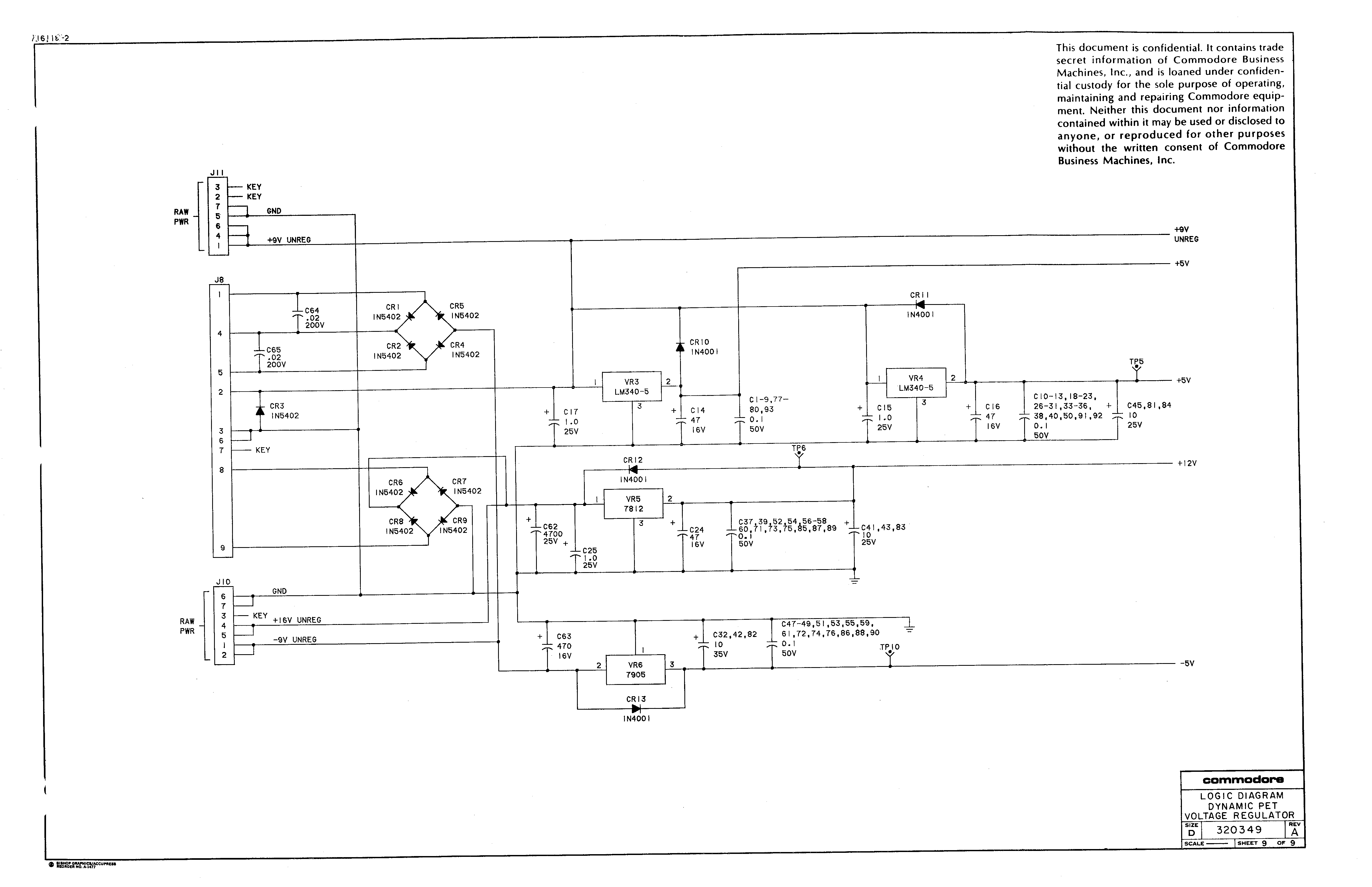
Sadly I do not have any information about the machine. Whether it was in working condition or an abandoned project. I will get on measuring Voltages tomorrow morning. I just spent the evening cleaning the board with dish soap and Q-tips. we have warm and dry summer nights now so it should be all dry in the morning. I will probably need some help with that too. I have found a ground, and i think i have found the 5V, but im not sure where to find the -5V and the 12V (I gathered this much from this here http://www.zimmers.net/anonftp/pub/cbm/ ... 0349-9.gif please correct me if im wrong.
Emmanuel
- Attachments
-
- the cleaned board
-
- Is this looking normal?
-
- or this? (more cleaning needed)
Re: Bought a PET - Not working ^^
The main voltages should be present on the 4 corners of the ram chips.
The 4116 family have
Pin 1 @ -5v
Pin 8 @ 12v
Pin 9 @ 5v
Pin 16 ground
The 4116 family have
Pin 1 @ -5v
Pin 8 @ 12v
Pin 9 @ 5v
Pin 16 ground