The scope is working correctly! I tested it's 1KHz output and it worked just fine, I also got 50Hz out of the oscillator, and the voltage was peaking around 2.5v.
Is the oscillator defective?
Help: Crystal Oscillator is not working.

Re: Help: Crystal Oscillator is not working.
Fifty Hertz?? That sounds suspiciously like ambient noise from the AC mains (assuming you're in a country that uses 50 Hz, such as UK and much of Europe). As well as the signal, have you attached the ground lead of your scope probe to ground on the project?
-- Jeff
-- Jeff
Last edited by Dr Jefyll on Wed Dec 23, 2020 10:36 pm, edited 1 time in total.
In 1988 my 65C02 got six new registers and 44 new full-speed instructions!
https://laughtonelectronics.com/Arcana/ ... mmary.html
https://laughtonelectronics.com/Arcana/ ... mmary.html
-
ProfessorCagan
- Posts: 23
- Joined: 22 Dec 2020
Re: Help: Crystal Oscillator is not working.
I live in the states, so I'd expect 60Hz if that were the case?
I've used probes quite a bit for troubleshooting lessons in Devices II, usually on OPAMPs. Admittedly we've never spent much time drawing schematics or creating actual circuits in my classes, we mostly went over theory and formulas.
But yes, the probe is connected correct,
I've used probes quite a bit for troubleshooting lessons in Devices II, usually on OPAMPs. Admittedly we've never spent much time drawing schematics or creating actual circuits in my classes, we mostly went over theory and formulas.
But yes, the probe is connected correct,
- Attachments
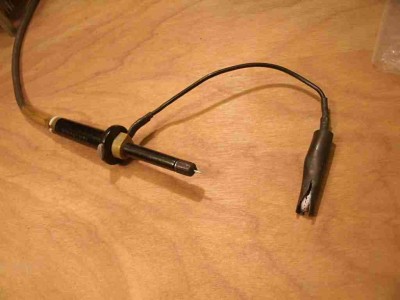
-
- Probe connected to GRD and CLK.
-
leepivonka
- Posts: 167
- Joined: 15 Apr 2016
Re: Help: Crystal Oscillator is not working.
On the scope: I don't see much for specifications on it, but it does mention 1Msps - does this mean it can do up to 1M samples per second? If that's true, it won't be able to reliably show the fundamental frequency of a 1MHz signal, let alone any higher multiples to show how sharp the edges are. The 50Hz signal you're seeing could be the beat between the oscillator signal & the scope's sampling rate.
On the oscillator: 2.5v peak could just barely meet TTL voltage levels ( >2.4v hi, <.8v lo).
Check the 6502 datasheet for your CPU version - this may not meet the clock input requirements.
You could improve the signal by adding a pull up resistor (try 470 ohm to +5v) or running it through a 74hct gate (try 1 section of a 74hct04).
Most 6502 variants can run at clock frequencys down to 100KHz, any some down to DC. Check the datasheet for your CPU version for details.
Re: Help: Crystal Oscillator is not working.
ProfessorCagan wrote:
But yes, the probe is connected correct,
What about the fourth pin on that oscillator? Besides the Gnd and power pin and the Output, some units also have an Enable input that needs to be tied high. As an experiment, I'd just go ahead and try attaching that pin to +5.
And your little test circuit could use a bypass cap, BTW.
-- Jeff
Edit:
leepivonka wrote:
The 50Hz signal you're seeing could be the beat between the oscillator signal & the scope's sampling rate.
Last edited by Dr Jefyll on Wed Dec 23, 2020 9:50 pm, edited 1 time in total.
In 1988 my 65C02 got six new registers and 44 new full-speed instructions!
https://laughtonelectronics.com/Arcana/ ... mmary.html
https://laughtonelectronics.com/Arcana/ ... mmary.html

Re: Help: Crystal Oscillator is not working.
If the oscillator is a bit fast for the scope, perhaps you can divide by 2, 4 or 8 using a TTL part, and check the output of that divider.
-
ProfessorCagan
- Posts: 23
- Joined: 22 Dec 2020
Re: Help: Crystal Oscillator is not working.
Leepivonka, I couldn't find the CPU's clock voltage requirement in its datasheet, but I'm gonna go ahead and try Dr. Jefyll's suggestion, and leave the results in this post.
Ok, so I continued to get around 50Hz measured when I tried connecting 5v to that last pin.
Ok, so I continued to get around 50Hz measured when I tried connecting 5v to that last pin.
- Attachments
-
- Test Oscillator
-
- Scope

Re: Help: Crystal Oscillator is not working.
ProfessorCagan wrote:
The scope is working correctly! I tested it's 1KHz output and it worked just fine, I also got 50Hz out of the oscillator, and the voltage was peaking around 2.5v.
But as leepivonka points out, it didn't occur to me to look at the 'scope specs. I don't see anything for sampling rate there, but it does say that the time base range starts at "10μs / Div", which is not a good sign; if it sampled fast enough to capture a 1 MHz waveform surely they wouldn't make you display ten cycles of it in a division, making it unreadable. (The picture of a running screen shows a 140 kHz waveform.) So yeah, I'm thinking that probably this 'scope can't be used to check this clock.
No fear, though; you can run the W65C02 at any speed, so if you can get hold of a slower crystal, or divide this one down per Ed's suggestion, that will let you check the clock. If neither of those options is handy, I'd start by hooking the clock back up to the CPU, pulling up/down the data bus to generate a NOP, and then trying your 'scope on the high address lines, which I hope might be down in a range that your 'scope will show. On a CPU running at 1 MHz, and at two cyles per NOP, A0 should be changing at 500 kHz, A1 at 250 kHz, and so on all the way up to A15 at 15.25 Hz. (Someone check my math there.) And this is exactly what I saw on both NMOS and early CMOS 6502s, last time I tried this out. However, I don't know if the W65C02 behaves in the same way, maintaining the address bus value throughout the entire cycle until it needs to change it.
(If this does work, you also now have built yourself a handy tester to see how high your 'scope goes. :-))
If this doesn't work, I'd do a quick check of the /RESET line, triggering your 'scope for a one-shot capture when you press the button, if it can do this. If you're having a good day it will look fine, but if the reset line is a big bouncing mess when you press the button, you might want to consider building a proper reset circuit.
If none of that works out, while you're waiting for a slower oscillator maybe try building a manual-step clock so that you can click a button to cycle the CPU, and see if that, with a NOP generator, produces some expected results on the address lines.
BTW, 32.768 kHz oscillators are really common and cheap, and well within the range of your 'scope unless the picture is a complete lie.
Curt J. Sampson - github.com/0cjs
Re: Help: Crystal Oscillator is not working.
Although packaged chips are quite robust, crystals are fragile mechanical systems: it might be worth noting that a crystal oscillator could be damaged in transit or by falling onto a hard surface.
So making sure you do have a clock signal is a crucial first step.
So making sure you do have a clock signal is a crucial first step.
Re: Help: Crystal Oscillator is not working.
The 32.768 kHz oscillator is a great idea. The CPU won't mind running that slowly, and there's cause to suspect the lower speed will make a world of difference regarding the 'scope.
Well, until a new oscillator is obtained, it might be worth testing the old one with a voltmeter (or multimeter). An attempt to read DC voltage on the output may seem counterintuitive, but it's better than nothing. What you'll get is the approximate average voltage. A reading of 0 or 5 volts surely indicates a defect, whereas a reading of 2.5V or slightly less suggests (doesn't prove) all is well.
Moreover, a multimeter may feature a Frequency range, which of course ought to indicate 1 MHz (assuming the meter can read that high).
-- Jeff
BigEd wrote:
a crystal oscillator could be damaged
Moreover, a multimeter may feature a Frequency range, which of course ought to indicate 1 MHz (assuming the meter can read that high).
-- Jeff
Last edited by Dr Jefyll on Thu Dec 24, 2020 2:56 pm, edited 1 time in total.
In 1988 my 65C02 got six new registers and 44 new full-speed instructions!
https://laughtonelectronics.com/Arcana/ ... mmary.html
https://laughtonelectronics.com/Arcana/ ... mmary.html
Re: Help: Crystal Oscillator is not working.
Dr Jefyll wrote:
Moreover, a multimeter may feature a Frequency range, which of course ought to indicate 1 MHz (assuming the meter can read that high).
That said, a 'scope provides significantly better information, so it's not worth spending additional money on a frequency counter unless it's significantly cheaper than buying a 'scope that can go to a couple of MHz or more.
Another tool that's useful when you don't have a 'scope is a logic probe, and some can actually identify high frequency signals. (E.g., a logic probe might be able to tell you whether that clock line is really switching between 0 and 1 TTL levels, or is just hovering around some intermediate voltage.)
Curt J. Sampson - github.com/0cjs
-
ProfessorCagan
- Posts: 23
- Joined: 22 Dec 2020
Re: Help: Crystal Oscillator is not working.
Ok, guys, I do have a meter that can read frequency, and to be honest, I don't know why I haven't tried it yet, slipped my mind I suppose.
So, I can either use the scope for checking pulled address lines, or the meter for checking the oscillator outright (if it can,) or I can purchase a slower crystal.
Then get back to debugging the CPU?
(Side questions, using a smaller crystal would let me see the LED's change correct, if it was slow enough of course?
When I last tried it, the LEDs that came on stayed on, and the ones that were off stayed off. I assume that is because was not receiving a clock signal?)
Thanks again for the help you've all given me so far, and I hope Christmas is treating you all well!
-
ProfessorCagan
- Posts: 23
- Joined: 22 Dec 2020
Re: Help: Crystal Oscillator is not working.
Ok, so, the oscillator works correctly, tested it with the multimeter, I should've done that from the beginning, would've saved us all a headache, I imagine, my apologies.
But now that it is out of the way, I'd still like to figure out (see quote below:)
But now that it is out of the way, I'd still like to figure out (see quote below:)
ProfessorCagan wrote:
(Side questions, using a smaller crystal would let me see the LED's change correct, if it was slow enough of course?
When I last tried it, the LEDs that came on stayed on, and the ones that were off stayed off. I assume that is because was not receiving a clock signal?)
When I last tried it, the LEDs that came on stayed on, and the ones that were off stayed off. I assume that is because was not receiving a clock signal?)
- Attachments
-
- Meter reading crystal's output.

Re: Help: Crystal Oscillator is not working.
Yes, a lower frequency crystal or crystal oscillator can will clock the 6502 microprocessor slower, hence it’s whole operation will be slower including the frequency that the address pins change.
With a NOP generator, the microprocessor will read the instruction (NOP - telling it to do a ‘No Operation’), it will then carry out NO register or ALU operation, but will increment the instruction register as normal. Then at the next cycle, it will put the new address on to the address bus (the A0 to A15 pins) and read the next instruction from the data bus (the D0 to D7 pins), which will still be a NOP. So it will repeat everything again and again.
Because the number on the address bus is being incremented, A0 will change the fastest, with each higher numbered address pin changing state at half the frequency compared to its lower numbered neighbour. This applies all the way up to the A15 pin.
So connect your ‘scope, or multimeter to each address pin in turn from A0 to A15 and see what you get.
Mark
Re: Help: Crystal Oscillator is not working.
ProfessorCagan wrote:
Ok, guys, I do have a meter that can read frequency, and to be honest, I don't know why I haven't tried it yet, slipped my mind I suppose.
ProfessorCagan wrote:
Ok, so, the oscillator works correctly, tested it with the multimeter...
Quote:
So, I can either use the scope for checking pulled address lines, or the meter for checking the oscillator outright (if it can,) or I can purchase a slower crystal.
Quote:
...using a smaller crystal would let me see the LED's change correct, if it was slow enough of course?
If the CPU with NOP pull-ups/downs on the data bus is working correctly, at 1 MHz the A15 line should be toggling at around 7.5 Hz. That may be too fast to see as actual blinking, depending on the particular conditions of the LED circuit, and of course each successively lower address line will be twice the rate of the previous. At 32.768 kHz A15 should be blinking at 0.25 Hz, or be on for two seconds followed by off for two seconds, which will be easily visible.
Quote:
When I last tried it, the LEDs that came on stayed on, and the ones that were off stayed off. I assume that is because was not receiving a clock signal?
So really, when things start going weird, it's often helpful to go back to the very start by checking the power lines, then the clock, then working out from there to every other signal in the system.
Curt J. Sampson - github.com/0cjs