Here we go:
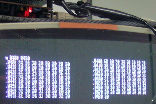
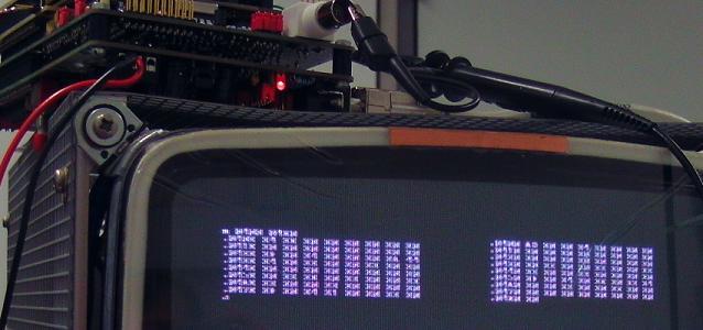
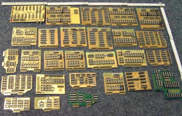
X50, experimental TTL implementation of a 6850, FAILED (that's why I had reversed the colors of the picture)
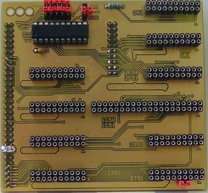
For "6850", plugged into the 1X51 backplane, we have:
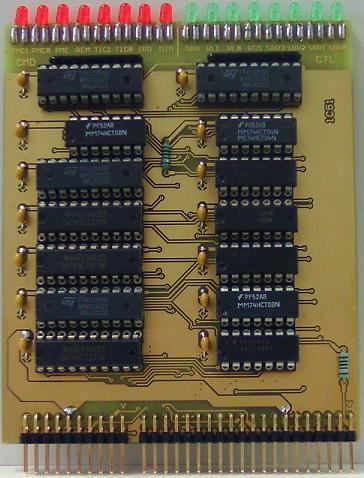
1* 1C50, control module
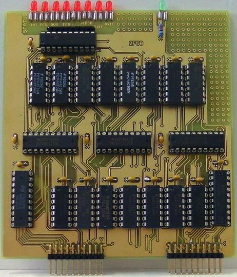
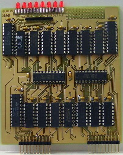
1* 2F50, flag and status module
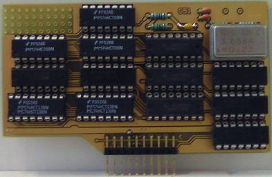
1* 2R51, receiver module
1* 2T51, transmitter module
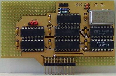
1* G50, baud rate generator module
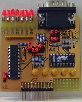
1* D51, RS232 level converter module
;-------------------------------------------------------------------------------------
X51, experimental TTL implementation of a 6551, FAILED (that's why I had reversed the colors of the picture)
For "6551" plugged into the 1X51 backplane, we have:
1* 1C51, control module
1* 2F51, flag and status module
1* 2R51, receiver module
1* 2T51, transmitter module
1* G51, baud rate generator module
1* D51, RS232 level converter module
;==================================================================
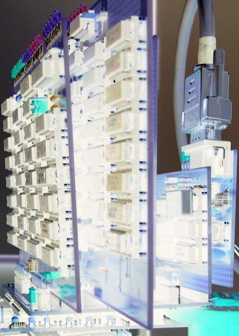
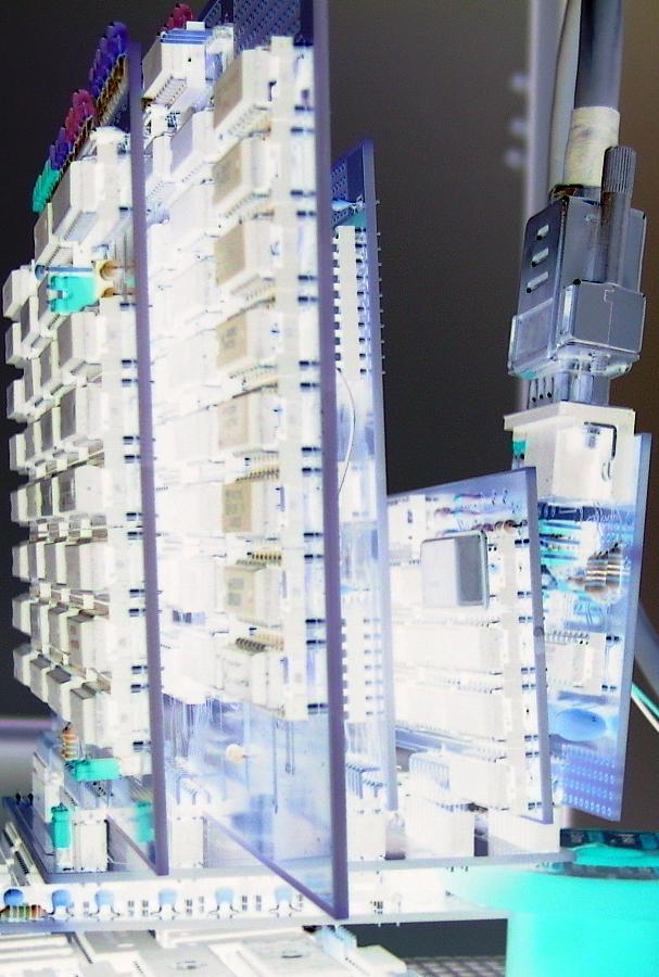
What had failed, was the RX part (we later are getting to it), and the rest of the circuitry mainly was/is untested.
Noticed something ?
For economical reasons, the TTL 6850 and the TTL 6551 project both had used these modules:
1* 1X51 backplane
1* 2T51, transmitter module
1* 2R51, receiver module //FAILED
1* D51, RS232 level converter module