HDL Implementation of Video Generator Test for 16-bit PVB's

Re: HDL Implementation of Video Generator Test for 16-bit PV
You could make a test pattern with wide alternating bars at the top, say 64 pixels of each color, followed by rows with 32 pixel bars, all the way down to single pixel alternating at the bottom.
-
ElEctric_EyE
- Posts: 3260
- Joined: 02 Mar 2009
- Location: OH, USA
Re: HDL Implementation of Video Generator Test for 16-bit PV
This may be abit off-topic, but have you ever seen the ORSOC Graphics Accelerator @opencores.org? Looks very impressive, says it is to be used with another VGA/LCD core for RGB output. I'm currently looking it over...
Re: HDL Implementation of Video Generator Test for 16-bit PV
ElEctric_EyE wrote:
This may be abit off-topic, but have you ever seen the ORSOC Graphics Accelerator @opencores.org? Looks very impressive, says it is to be used with another VGA/LCD core for RGB output. I'm currently looking it over...
-
ElEctric_EyE
- Posts: 3260
- Joined: 02 Mar 2009
- Location: OH, USA
Re: HDL Implementation of Video Generator Test for 16-bit PV
Yes, I see it takes 10,000 slice LUTs and was made for a XC6SLX45 on the Digilent Atlys board. This 320-pin Spartan 6 that Digilent uses, is the smallest BGA package version of the XC6SLX45 (27,288 slice LUTs). Our little XC6SLX9 only has 5720.
But it still may be a design worth referring to, and removing some extras in order to take advantage of the overall design of triangle plotting. Too much may have to be removed though, because it must work in unison with the VGA_LCD core previously mentioned, and this would take even more space in the FPGA. Not to mention the CPU core.
May be best to stay on course with humble beginnings, but with an eye towards what can be achieved...
I thought I'd mention an article I happened across today, a very recent article dated June 4, 2012 regarding the 'ORGFXSoC' effort is here.
And here on ProjectVGA.
-
ElEctric_EyE
- Posts: 3260
- Joined: 02 Mar 2009
- Location: OH, USA
Re: HDL Implementation of Video Generator Test for 16-bit PV
And another similar project, although it uses a Spartan 3, called openVGA with verilog HDL available on sourceforge. Associated homepage is here.
EDIT: Tomorrow, I need to do some reading on the 'VGA/LCD Core v2.0 Specifications'. It has info I need to learn about video bandwidth...
EDIT: Tomorrow, I need to do some reading on the 'VGA/LCD Core v2.0 Specifications'. It has info I need to learn about video bandwidth...
-
ElEctric_EyE
- Posts: 3260
- Joined: 02 Mar 2009
- Location: OH, USA
Re: HDL Implementation of Video Generator Test for 16-bit PV
Such a struggle, but I finally made a successful test to alternate black and white pixels straight from the FPGA to the videoDAC. So far I just tested 320x200 resolution. I don't see anything out of order. I've attached the zipped ISE 13.4 project file.
EDIT: Seeing a moire pattern side effect at 1280x1024 resolution. Also, 320x200 not such a square pixel. Might have to go for 320x240 as a lower resolution.
Code: Select all
module VDACif( input clk108,
					input hstart,
					input vstart,
					input hblank,
					output reg [4:0] Red_data,
					output reg [5:0] Green_data,
					output reg [4:0] Blue_data,
					output reg DACBLANKn = 1
					);

reg countflag;
reg [8:0] Hcount;
reg [7:0] Vcount;

always @(posedge clk108)
		if ( !hblank )
			Hcount <= Hcount + 1;
		else if ( hblank )
			Hcount <= 0;

always @(posedge clk108)
      if ( hstart )
		   countflag <= 1;	//countflag active in display area
      else if ( hblank )
         countflag <= 0;

always @(posedge clk108)
	if ( countflag )
		begin
			Red_data <= hblank ? 0 :
					Hcount[0] ? 0 :
					5'b11111;
			Green_data <= hblank ? 0 :
					  Hcount[0] ? 0 :
					  6'b111111;
			Blue_data <= hblank ? 0 :
					 Hcount[0] ? 0 :
					 5'b11111;
	end

endmodule
- Attachments
-
- PVBSSOtest.zip
- (1.07 MiB) Downloaded 78 times
Re: HDL Implementation of Video Generator Test for 16-bit PV
Now try a blue border around the pattern.
-
ElEctric_EyE
- Posts: 3260
- Joined: 02 Mar 2009
- Location: OH, USA
Re: HDL Implementation of Video Generator Test for 16-bit PV
Arlet wrote:
Now try a blue border around the pattern.
Code: Select all
module VDACif( input clk108,
					input hstart,
					input vstart,
					input hblank,
					output reg [4:0] Red_data,
					output reg [5:0] Green_data,
					output reg [4:0] Blue_data,
					output reg DACBLANKn = 1
					);

reg countflag;
reg [8:0] Hcount;
reg [7:0] Vcount;

always @(posedge clk108)
		if ( !hblank )
			Hcount <= Hcount + 1;
		else if ( hblank )
			Hcount <= 0;

always @(posedge clk108)
      if ( hstart )
		   countflag <= 1;	//countflag active in display area
      else if ( hblank )
         countflag <= 0;

always @(posedge clk108)
	if ( countflag )
			Red_data <= hblank ? 0 :
						   Hcount[0] ? 0 :
							5'b11111;
	else if ( hblank )
			Red_data <= 0;

always @(posedge clk108)
	if ( countflag )
			Green_data <= hblank ? 0 :
							  Hcount[0] ? 0 :
							  6'b111111;
	else if ( hblank )
			Green_data <= 0;

always @(posedge clk108)
	if ( countflag )
			Blue_data <= hblank ? 0 :
						    Hcount[0] ? 0 :
							 5'b11111;
	else if ( hblank )
			Blue_data <= 5'b11111;

endmodule
Re: HDL Implementation of Video Generator Test for 16-bit PV
Try running a simulation. It will show you the timing diagrams, and then it should be easier to understand what's going wrong. But this is tricky stuff. I still remember the first designs I made. It took days before it finally worked, and then I looked at the design and wondered why it took so long to write 50 lines 
-
ElEctric_EyE
- Posts: 3260
- Joined: 02 Mar 2009
- Location: OH, USA
Re: HDL Implementation of Video Generator Test for 16-bit PV
Ok, I fixed my code to the following which seems like it should work but it still has the same action:
Sim's on these video circuits are so long... I will continue tomorrow.
Code: Select all
module VDACif( input clk108,
					input hstart,
					input vstart,
					input hblank,
					output reg [4:0] Red_data,
					output reg [5:0] Green_data,
					output reg [4:0] Blue_data,
					output reg DACBLANKn = 1
					);

reg countflag;
reg [8:0] Hcount;
reg [7:0] Vcount;

always @(posedge clk108)
		if ( !hblank )
			Hcount <= Hcount + 1;
		else if ( hblank )
			Hcount <= 0;

always @(posedge clk108)
      if ( hstart )
		   countflag <= 1;	//countflag active in display area
      else if ( hblank )
         countflag <= 0;

always @(posedge clk108)
	if ( countflag )
			Red_data <= Hcount[0] ? 0 :
							5'b11111;
	else if ( hblank )
			Red_data <= 0;

always @(posedge clk108)
	if ( countflag )
			Green_data <= Hcount[0] ? 0 :
							  6'b111111;
	else if ( hblank )
			Green_data <= 0;

always @(posedge clk108)
	if ( countflag )
			Blue_data <= Hcount[0] ? 0 :
							 5'b11111;
	else if ( hblank )
			Blue_data <= 5'b11111;

endmodule
Arlet wrote:
Try running a simulation. It will show you the timing diagrams, and then it should be easier to understand what's going wrong. But this is tricky stuff. I still remember the first designs I made. It took days before it finally worked, and then I looked at the design and wondered why it took so long to write 50 lines
Re: HDL Implementation of Video Generator Test for 16-bit PV
Quote:
Sim's on these video circuits are so long... I will continue tomorrow.
-
ElEctric_EyE
- Posts: 3260
- Joined: 02 Mar 2009
- Location: OH, USA
Re: HDL Implementation of Video Generator Test for 16-bit PV
Arlet wrote:
Quote:
Sim's on these video circuits are so long... I will continue tomorrow.
-
ElEctric_EyE
- Posts: 3260
- Joined: 02 Mar 2009
- Location: OH, USA
Re: HDL Implementation of Video Generator Test for 16-bit PV
Well this was the best I could do without help:
And the result:
Code: Select all
module VDACif( input clk108,
					input hstart,
					input vstart,
					input hblank,
					input vblank,
					output reg [4:0] Red_data = 0,
					output reg [5:0] Green_data = 0,
					output reg [4:0] Blue_data = 0,
					output reg DACBLANKn = 1
					);

reg countflag;
reg Alt;												//

always @(posedge clk108)
      if ( hstart )
         countflag <= 1;						//countflag active in display area
      else if ( hblank | vblank )
         countflag <= 0;

always @(posedge clk108)						//Alternate on-off pixel value
	//if ( countflag )
		Alt <= ~Alt;

always @(posedge clk108)						//outgoing data to videoDAC
      if ( countflag ) begin
			if ( Alt ) begin                               //white pixel
				Red_data <= 5'b11111;
				Green_data <= 6'b111111;
				Blue_data <= 5'b11111;
			end
				else begin                            //black pixel
					Red_data <= 0;
					Green_data <= 0;
					Blue_data <= 0;
				end
		end
		else if ( vblank | hblank ) begin               //border
				Red_data <= 0;
				Green_data <= 0;
				Blue_data <= 5'b11111;
			end

endmodule
Re: HDL Implementation of Video Generator Test for 16-bit PV
Instead of picking colors based on countflag and hblank/vblank, you could make a x/y counter.
Restart x = 0 at htstart, and increment x when countflag = 1. If you get it right, x should go from 0 to 639 (for normal VGA). Then, you can select a pixel color based on x value.
Restart x = 0 at htstart, and increment x when countflag = 1. If you get it right, x should go from 0 to 639 (for normal VGA). Then, you can select a pixel color based on x value.
-
ElEctric_EyE
- Posts: 3260
- Joined: 02 Mar 2009
- Location: OH, USA
Re: HDL Implementation of Video Generator Test for 16-bit PV
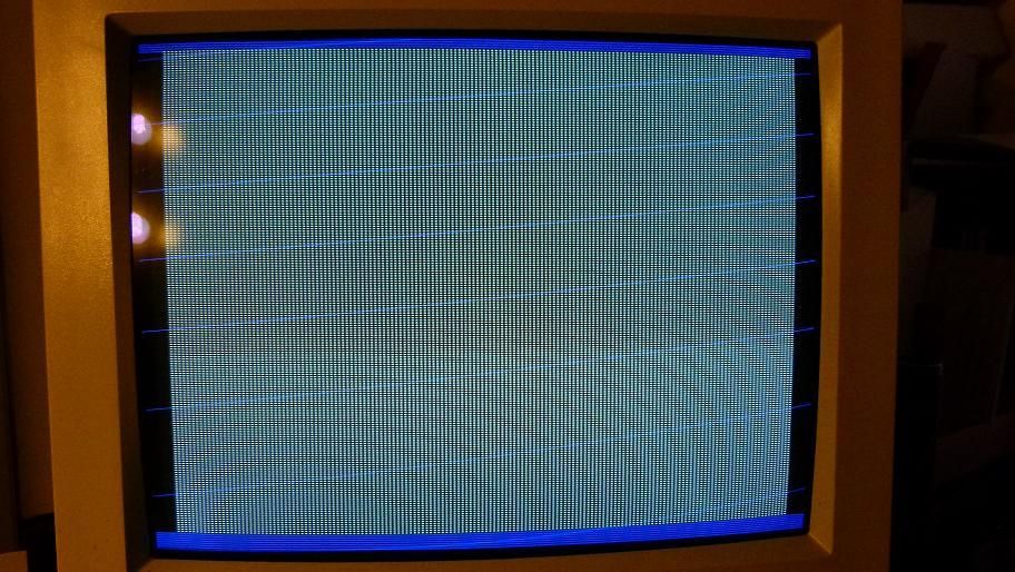
Counters, yes I started with counters earlier. So I modified my code and have this now, with same action in previous pic:
Much easier to see in sim now I can see the X counter, it is resetting properly...
Now that nasty retrace going across the back of the screen, how do we get rid of it? Is it possible for a different colored border without using the videoDAC DACBLANK signal? or will we be forced to use black borders?
EDIT: video is presently 320x200.
Code: Select all
module VDACif( input clk108,
					input hstart,
					input vstart,
					input hblank,
					input vblank,
					output reg [4:0] Red_data = 0,
					output reg [5:0] Green_data = 0,
					output reg [4:0] Blue_data = 0,
					output reg DACBLANKn = 1
					);

reg countflag;
reg [8:0] X = 0;
reg [7:0] Y = 0;

always @(posedge clk108)
      if ( hstart )
         countflag <= 1;						//countflag active in display area
      else if ( hblank | vblank )
         countflag <= 0;

always @(posedge clk108)
	if ( countflag )
		X <= X + 1;
		else
			X <= 0;

always @(posedge clk108)						//outgoing data to videoDAC
		if ( vblank | hblank ) begin
			Red_data <= 0;
			Green_data <= 0;
			Blue_data <= 5'b11111;
		end
			else if ( X[0] ) begin
				Red_data <= 5'b11111;
				Green_data <= 6'b111111;
				Blue_data <= 5'b11111;
			end
				else begin
					Red_data <= 0;
					Green_data <= 0;
					Blue_data <= 0;
				end

endmodule
Now that nasty retrace going across the back of the screen, how do we get rid of it? Is it possible for a different colored border without using the videoDAC DACBLANK signal? or will we be forced to use black borders?
EDIT: video is presently 320x200.