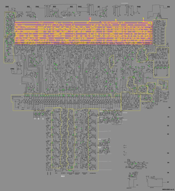
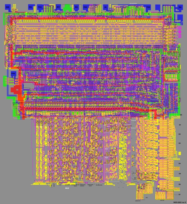
Completed random logic at trans-level

Random logic interconnections with other 6502 parts:
Inputs
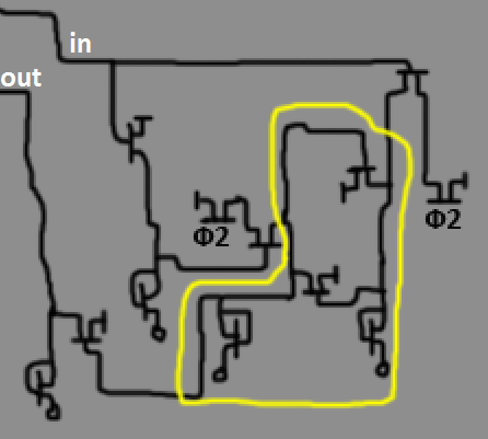
PHI1,PHI2: timing
Reset0: from RST pin
NMIG: from NMI pin logic
IRQP: from IRQ pin logic
/IR5: from instruction register, to determine CLC/SEC and others
SO: from SO pin, set V-flag
RDY: from RDY pin
BRKDONE, VEC: from interrupt priority logic
2 inputs from predecode logic.
129 lines from PLA.
AVR: overflow out from ALU
ACR: carry out from ALU
Outputs
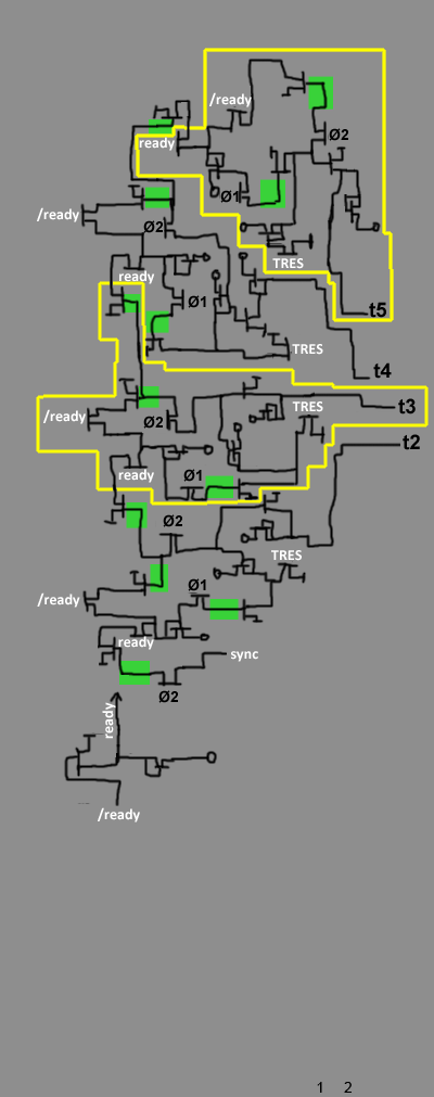
TRES: reset T-counter
sync: shift T-counter, additionally output to SYNC pin
T0, T1X: first two steps of instruction decoding, to PLA
R/W: Goes to R/W pin and data latch
fetch: Force instruction register to load from Predecode Register
VEC0: to interrupt priority logic, when BRK detected
48 output drivers, to control bottom part.
Also random logic is connected with internal data bus (DB) to exchange status reg (flags).