6502 and 16550 UART Problem

Building your first 6502-based project? We'll help you get started here.
maewn21
Posts: 14
Joined: 28 Jan 2021
Location: Thailand

6502 and 16550 UART Problem

Post by maewn21 »

This is the first 6502 project I've ever built and also the first time I'm using the 16550 UART.

I'm trying to initialize a 16550 and send characters 0 to 255 in an endless loop via a max232 to my PC.
I was expecting some unprintable characters and somewhere in between the whole ASCII char set.
However all I get in putty is gibberish.
I've tried different baud rates 1200, 9600, 38400
I've tried another USB to serial adapter,
I've tried another Crysal osc with the same frequency (1.8432Mhz),
I've tried another 16550 chip (the other is a 16C552 actually),
But still all i get is gibberish so i figured that the problem is likely in my assembly code.

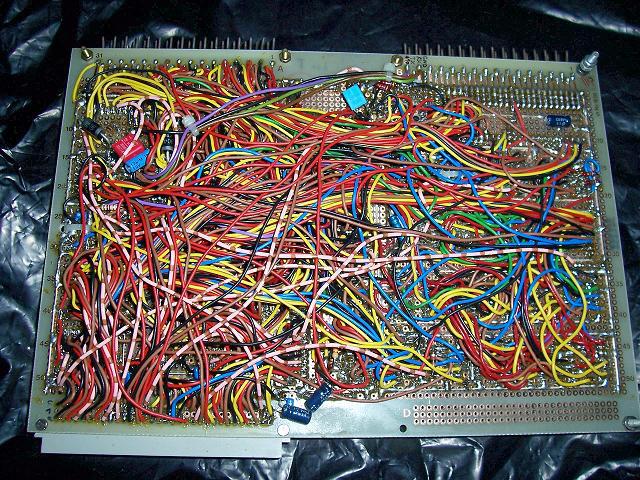
Anyways just in case I've done something wrong with the hardware I attach a rough schematic too.
Data and Address lines that are not shown in the drawing are straight connected to every chip that needs them. All IC's have 100n decoupling capacitors near them.

Does anyone have an idea how to get the UART running correctly? Thanks.

Memory map:
0000-7FFF RAM
8000-BFFF IO
C000-FFFF ROM

Here my code:

Code: Select all

INIT:
	LDA	#$80	; DLAB=1 open special control register
	STA	$8003

	LDA	#$0C 	; $60 = 1200kbps, $0C = 9600kbps, $03 = 38400kbps
	STA	$8000	; DLL

	LDA	#$00
	STA	$8001	; DLM

	LDA	#$03
	STA	$8003	; Set 8N1 byte framing: 8-bit data, no parity, 1 stop bit, reset DLAB Flag.

	LDY	#$00

LOOP:
	LDA	$8005		; Fetch the control register.
	AND	#$20		; Bit5 will be set to 1 if UART is ready to send.
	CMP	#$20
	BNE	LOOP

	STY	$8000		; Transmit character in register A to UART.
	INY
	JMP LOOP
Attachments
Glue logic and a list of IC pins (with pin number and name) wired to ground, VCC or held high with pull-up resistors.
The kind of gibberish i get in putty.
User avatar
barrym95838
Posts: 2056
Joined: 30 Jun 2013
Location: Sacramento, CA, USA

Re: 6502 and 16550 UART Problem

Post by barrym95838 »

The pattern appears to be repetitive and stable, so the first thing I would check is the compatibility of the parity and stop bit formats between transmitter and receiver.

I would also try to avoid sending non-printable characters, due to the possibility of triggering an unexpected mode change in the receiver.

Code: Select all

   ...
   LDY   #$20

LOOP:
   LDA   $8005      ; Fetch the control register.
   AND   #$20       ; Bit5 will be set to 1 if UART is ready to send.
   BEQ   LOOP

   STY   $8000      ; Transmit character in register Y to UART.
   INY
   BPL   LOOP
   BMI   LOOP-2
Got a kilobyte lying fallow in your 65xx's memory map? Sprinkle some VTL02C on it and see how it grows on you!

Mike B. (about me) (learning how to github)
SamCoVT
Posts: 344
Joined: 13 May 2018

Re: 6502 and 16550 UART Problem

Post by SamCoVT »

I agree with everything Mike B. said and would add the following:

Check the /BAUDOUT pin (pin 15) with a scope or frequency counter of you have one - it should be running at 16x the baud rate you want.

Don't send data continuously - at a minimum, have a pause longer than 1 character (eg. 1.04ms for 10-bits of 9600 8N1) every so often.

When you open your PuTTY connection, it will open the COM port which will then wait for the first 0 it sees as the start of the frame (1 is IDLE for this kind of serial). It might see a 0 in the middle of one of your bytes and try to start there. The PC will usually silently throw away any bytes that have frame errors (eg. the stop bit (which should be a 1) is not found at the end) and just try again, but it might try in the middle of a byte again. With no pause in the data, it might never get it right.

If your application really needs to send continuous data, then open PuTTY *FIRST* with an idle serial port and then have your 6502 board start sending data. That guarantees that the first 0 on the bus is an actual start bit.

My question for you is what kind of seral to USB port adapter are you using? Does it have a 9-pin plug on it? You'll need a level shifter if you want to connect to that kind of port. RS-232C uses (-3 to -25V) to send a logic 1 and (+3 to +25) to send a logic zero. You *CAN* put 0-5V type logic into *SOME* of these adapters, but note that you need to put 0V in for a logic 1 and 5V (more than 3V, really) in for a logic level 0, so you may need to invert your data. That's not really approved usage and you really should have a level converter (like a max232 or max3232 or equivalent) if interfacing to a 9-pin port. If you have an FTDI-to-TTL type cable, then you should be OK hooking that directly up to your 16550.

The good news is that you are getting something, which implies you've done a lot correctly to get your hardware working, and your address decoding is *probably* working correctly.

One last note: PuTTY treats some special characters as commands that can result with gibberish on the screen - sticking with the printable characters is definitely recommended.
maewn21
Posts: 14
Joined: 28 Jan 2021
Location: Thailand

Re: 6502 and 16550 UART Problem

Post by maewn21 »

Sadly I don't have a Scope,
however #BAUDOUT reads 153600 Hz on the frequency counter which divided by 16 equals 9600 and therefore should be corerct.

I have a MAX232 connected to the 16550.
Im using a USB to TTL serial adapter (CP210x based) with another MAX232 hooked up to it. (So in this case it's basically two MAX232 facing each other. Works fine with other projects I've built)
I also have tried another USB to serial adapter (PL2303 based if I remember right), this one is a real RS232 adapter with a DB9 connector.
It's the same pattern I'm seeing with both of them. I've even hooked up the TTL one directly to the 16550 just to have it tried.

From my understanding I've set the 16550 to 8N1 with no parity and 1 stop bit. I have set up putty accordingly.
However I have played around with all kinds of data bit, stop bit and parity options in putty just to rule out the possibility. (didn't fix the problem)

Code: Select all

   LDA   #$03
   STA   $8003   ; Set 8N1 byte framing: 8-bit data, no parity, 1 stop bit, reset DLAB Flag.
Also I've followed Mike B's advice to not send unprintable characters and start with char 0x20, which did change the pattern I'm seeing a little bit but still nothing close to resembling the ASCII char set.

Then i have tried to implement a delay between every character by having a loop of NOP's in between every char. If I've got the assembly right this should loop 255 times and then go on with whatever comes after BPL DELAY.

Code: Select all

	LDX #$00
DELAY:
	NOP
	NOP
	NOP
	NOP
	NOP
	NOP
	NOP
	NOP
	NOP
	NOP
	INX
	BPL DELAY
However having this delay implemented I receive something completely different in putty. Something that confuses me even more than I have been before.
Attachments
puttynew.jpg
User avatar
MichaelM
Posts: 761
Joined: 23 Apr 2012
Location: Huntsville, AL

Re: 6502 and 16550 UART Problem

Post by MichaelM »

Recommend using capital U as your test character. When your format is 8N1, the U is a 50% duty cycle square wave. If you're feeding the UART the character with no delays, then the frequency counter should read 4800 Hz. Once you have this, then you can try the other printable characters.
Michael A.
User avatar
ttlworks
Posts: 1464
Joined: 09 Nov 2012
Contact:

Re: 6502 and 16550 UART Problem

Post by ttlworks »

Capital U is hexadecimal $55, binary 01010101.

It's been 20 years that I had tinkered with the 16550, and it wasn't 6502 related,
but to me it looks like your schematic and your code are supposed to work.

Would be nice if you could post photos of your hardware, maybe we are missing something obvious.

BTW: you better avoid transmitting ESC, that's hexadecimal $1B, decimal 27.
User avatar
BigDumbDinosaur
Posts: 9425
Joined: 28 May 2009
Location: Midwestern USA (JB Pritzker’s dystopia)
Contact:

Re: 6502 and 16550 UART Problem

Post by BigDumbDinosaur »

barrym95838 wrote:
The pattern appears to be repetitive and stable, so the first thing I would check is the compatibility of the parity and stop bit formats between transmitter and receiver.

I would also try to avoid sending non-printable characters, due to the possibility of triggering an unexpected mode change in the receiver.

Code: Select all

   ...
   LDY   #$20

LOOP:
   LDA   $8005      ; Fetch the control register.
   AND   #$20       ; Bit5 will be set to 1 if UART is ready to send.
   BEQ   LOOP

   STY   $8000      ; Transmit character in register Y to UART.
   INY
   BPL   LOOP
   BMI   LOOP-2
And for a more compact loop that doesn't send the rubout character to the terminal...

Code: Select all

  ...
         LDA #%00100000        ;test mask
         LDY #$20              ;ASCII space
;
LOOP     BIT $8005             ;UART ready?
         BEQ LOOP              ;no
;
         STY $8000             ;Transmit character in register Y to UART.
         INY
         CPY #$7F              ;end of ASCII series?
         BCC LOOP              ;no, send next
;
         JMP LOOP_2            ;yes, exit loop (BRA LOOP_2 if 65C02)
x86?  We ain't got no x86.  We don't NEED no stinking x86!
maewn21
Posts: 14
Joined: 28 Jan 2021
Location: Thailand

Re: 6502 and 16550 UART Problem

Post by maewn21 »

ttlworks wrote:
Capital U is hexadecimal $55, binary 01010101.

It's been 20 years that I had tinkered with the 16550, and it wasn't 6502 related,
but to me it looks like your schematic and your code are supposed to work.

Would be nice if you could post photos of your hardware, maybe we are missing something obvious.

BTW: you better avoid transmitting ESC, that's hexadecimal $1B, decimal 27.
I have not tried sending U's yet, but I will as soon as I get home. However I have some pictures of the hardware at hand.
The MAX232 is on a separate board since I don't have enough of them to stick one on every board that I build (the MAX232 boards work fine with other projects, however could the wire length to these boards be a problem? Maybe the Output of the 16550 is not as strong as the ATmega chips I usually use it with?!).
Attachments
a view on the wiring that is mostly under the IC's however I have taken this picture while i was building it, so there are still some wires missing in this picture and I am not keen on pulling out all the IC's just to make another photo.
bottom side of the board
The whole thing including the two mentioned MAX232 boards.
User avatar
ttlworks
Posts: 1464
Joined: 09 Nov 2012
Contact:

Re: 6502 and 16550 UART Problem

Post by ttlworks »

IMHO the problem can't be related to the MAX232, because then the pattern on the screen wouldn't be that repetive.

To me, it feels more like something goes wrong with the initialisation of the UART and/or with writing characters into the UART TX register on hardware level.

Would suggest to check the wiring of the bus interface of the UART.
From your photos, it looks like D7..D0 are connected correctly.
Please check, if AS is tied to GND indeed, and if A2..0 are connected correctly.
Also, please check the 74HCT00 and 74HCT04 wiring, to be sure that there is nothing wrong with /IOCE, /WE, /RD.


For your next build, I would suggest not to have wires below the IC sockets (for simplifying debugging/modifying the hardware),
also it would be better to use the more expensive IC sockets with precision pins (because > 10 times of plugging/unplugging a chip won't do good to the sockets you are using).

Another trick for simplifying debugging is to stick with the resistor color code for the wires of the bus lines,
like D0=black, D1=brown, D2=red, D3=yellow (if you can't buy orange), D4=black again etc.

Another trick is to have labels covering the top of the ICs, with printed info which signal is on which IC pin (so you won't have to look into the schematics too often).
User avatar
ttlworks
Posts: 1464
Joined: 09 Nov 2012
Contact:

Re: 6502 and 16550 UART Problem

Post by ttlworks »

If you want to roughly measure frequency, but you lack an oscilloscope and a frequency counter,
one option would be to build a binary counter from, let's say, 74HCT393 chips.

For instance, if you have a 12 Bit counter with the outputs Q11..Q0,
and a LED tied to Q11 (don't forget the resistor in between) would be blinking at ca. 1.17 times per second,
you know that the counter is clocked with 1.17Hz * 2^12 = ca. 4792Hz.

Hope, this helps.
maewn21
Posts: 14
Joined: 28 Jan 2021
Location: Thailand

Re: 6502 and 16550 UART Problem

Post by maewn21 »

OK I tried to send only capital U's which gives me a reading of 1280Hz +- a few Hz jumping up and down on the TX pin using this loop:

Code: Select all

LOOP:
	LDA	UART5	; Fetch the control register.
	AND	#$20	; Bit5 will be set to 1 if UART is ready to send.
	BEQ	LOOP

	LDY #$55
	STY UART0

	JMP LOOP
I thought waiting for the UART in this loop might cause this low reading so i tried to just write U's without waiting for the UART using the following loop. However all I've got is about 200Hz on the TX pin. Ergo the faster I write to the UART the less comes out of TX, which I think suggests that the problem really lies somewhere with the /IOCE, /WE, /RD lines.

Code: Select all

LOOP:
	LDY #$55
	STY UART0

	JMP LOOP
ttlworks wrote:
IMHO the problem can't be related to the MAX232, because then the pattern on the screen wouldn't be that repetive.

To me, it feels more like something goes wrong with the initialisation of the UART and/or with writing characters into the UART TX register on hardware level.

Would suggest to check the wiring of the bus interface of the UART.
From your photos, it looks like D7..D0 are connected correctly.
Please check, if AS is tied to GND indeed, and if A2..0 are connected correctly.
Also, please check the 74HCT00 and 74HCT04 wiring, to be sure that there is nothing wrong with /IOCE, /WE, /RD.


For your next build, I would suggest not to have wires below the IC sockets (for simplifying debugging/modifying the hardware),
also it would be better to use the more expensive IC sockets with precision pins (because > 10 times of plugging/unplugging a chip won't do good to the sockets you are using).

Another trick for simplifying debugging is to stick with the resistor color code for the wires of the bus lines,
like D0=black, D1=brown, D2=red, D3=yellow (if you can't buy orange), D4=black again etc.

Another trick is to have labels covering the top of the ICs, with printed info which signal is on which IC pin (so you won't have to look into the schematics too often).
I've checked A0..A2 are connected correctly and AS is wired to ground as well.
So I guess the problem really must be somewhere with the 74HCT logic or the wiring around there. I'll go thru the whole board checking for shorts between bus lines and correct wiring and post an update once I've done that.

Thanks for the hint with the wire colors using resistor color code. I haven't thought of that yet. That'll make it a a lot easier to debug than just one color for each bus.

This actually is one of the very few builds where I've crammed so many wires under the sockets since I thought looping this amount of wires around the sockets might take up too much space and the local parts shop here has got only one size of perfboard. (wasn't fun to do that anyways since I soldered the sockets in first)

Regarding the IC sockets I'm well aware that they are not very durable but they usually do the job well enough as it wasn't planned to run into a mysterious problem that forces me to swap the memory a few dozen times. I do by the way prefer this kind of socket over precision sockets since precision sockets make bending or breaking off IC legs too easy and its also difficult to stick salvaged parts with a little solder residue on the pins in those.
maewn21
Posts: 14
Joined: 28 Jan 2021
Location: Thailand

Re: 6502 and 16550 UART Problem

Post by maewn21 »

I've got it working!!!

After checking the wiring and not finding anything wrong I went thru my IC boxes looking for some 74HCT replacements to just eliminate the possibility that one of them is faulty. I found some and replacing them didn't solve the problem either. However while going thru the boxes I did find a third 16550 and this one just works. So it seems both IC's I tried before are faulty (how small is the chance of having two faulty IC's from different manufacturers producing similar gibberish?!)

Thank you everyone for your help and suggestions. I did even learn a few assembly things in the process, especially how to make efficient loops.
Attachments
it works and I am seriously so happy about it that I might actually enjoy watching the ASCII char set printing over and over for half an hour.
User avatar
BigDumbDinosaur
Posts: 9425
Joined: 28 May 2009
Location: Midwestern USA (JB Pritzker’s dystopia)
Contact:

Re: 6502 and 16550 UART Problem

Post by BigDumbDinosaur »

maewn21 wrote:
However while going thru the boxes I did find a third 16550 and this one just works.

What was your source for the UARTs? If eBay, there is no telling what you were sold. Also, it could be the UART was damaged by ESD, which is always lurking during the cold months.
x86?  We ain't got no x86.  We don't NEED no stinking x86!
maewn21
Posts: 14
Joined: 28 Jan 2021
Location: Thailand

Re: 6502 and 16550 UART Problem

Post by maewn21 »

BigDumbDinosaur wrote:
maewn21 wrote:
However while going thru the boxes I did find a third 16550 and this one just works.

What was your source for the UARTs? If eBay, there is no telling what you were sold. Also, it could be the UART was damaged by ESD, which is always lurking during the cold months.
The 16550 are all salvaged from old Mainboards and ISA I/O cards, as is the SRAM.

The 6502 is from China tho, from the looks I'd say the original marking has been sanded off. I've got two of them, both DIP packages look exactly the same with the small circle in the top corner and the marking "SB59" and Taiwan on the bottom. From the current draw (~150mA for the whole board) I'd say they are probably real, just NMOS versions remarked. I don't really mind about them being NMOS or the current draw, I just wanted to play around with some 6502 for the first time ever. At least I got 6502's and not some useless random IC with a fresh marking. (I did buy them fully aware of that I might get remarked or even worse complete fake chips since I could not find another source for these.)
Last edited by maewn21 on Fri Jan 29, 2021 5:18 pm, edited 1 time in total.
User avatar
BigEd
Posts: 11463
Joined: 11 Dec 2008
Location: England
Contact:

Re: 6502 and 16550 UART Problem

Post by BigEd »

Great to see a result!
Post Reply