6502.org Forum  Projects  Code  Documents  Tools  Forum
It is currently Fri Nov 22, 2024 2:07 pm

All times are UTC


Post new topic Reply to topic  [ 16 posts ]  Go to page 1, 2  Next
Author Message
 Post subject: z50 Bus CPU & Logic Card
PostPosted: Sun Mar 05, 2023 7:16 am 
Offline

Joined: Sun Mar 05, 2023 6:49 am
Posts: 9
Hi y'all, long time reader and first time poster.

I've been enjoying my breadboard build, and an Apple 1 SBC from eBay, but I want to put copper (and my money) where my mouth is and build out some PCBs. I also own a lot of gear from the RC2014 and "Small Computer Central" ecosystems, and because of that, I've decided to design a z50 Bus card. If you don't know it, z50 is a hobbyist bus designed by Ole Lians and is well documented. Specification is here: http://linc.no/products/z50bus/.

They describe how to adapt a 6502 to the bus, so I took that as a starting place, along with the 6502 primer and lots of posts here on the forum.

Attachment:
File comment: 3d render
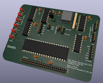
Screen Shot 2023-03-04 at 11.08.20 PM.png
Screen Shot 2023-03-04 at 11.08.20 PM.png [ 1.56 MiB | Viewed 39226 times ]


My board is designed to provide the CPU and bus logic signals, and to be compatible with the following cards:

As well as being generally compatible with other z50 bus cards that don't rely on the z80's special interrupt handling (e.g. not the z80 CTC/PIO/SIO accessories).

The board generates the following z50 bus signals.
  • /RD and /WR (thanks to BDD's great circuit)
  • /IOReq at $4000-$8000 (thanks to Garth's memory map
  • /MReq (simple NOT /IOReq)
  • /M1 (simple NOT SYNC)

In order to support the standard z50/z80 memory map and existing memory cards, there is a jumper to export either A15 or /A15 to the bus on the A15 line. By selecting the /A15 option, the existing memory card can be used, its RAM and Flash accesses will be flipped.

There's eight 1-bit inputs and eight 1-bit outputs onboard, selected by the /PORT signal. A 74HC4075 generates /PORT as well as the chip enables (/PORT & /IOReq & the appropriate read or write). These offer a bit-banged UART, two status LEDs that can be controlled by the user program, and four bits on headers for user experiments. The output circuit comes from SCC's SC519/SC516 designs, and I just tried to flip/reverse it for the input port.

BE/RDY/SO/VP/ML are all just tied high (or left floating where appropriate) but a header exposes them, in case I want to bodge on some logic later. The bus standard specifies /WAIT and /HALT signals but no existing peripherals use them, and I haven't quite figured out what splitting RDY for that would look like anyway.

I'm attaching a draft schematic (in color and B&W). I'd appreciate any comments, suggestions, or pointing out any mistakes I've made. All logic is 74HCxx series (even if I maybe forgot to update the symbol) running at 5V.

A few specific points I'd like feedback on:
1) the single bit ports all use the LSB of the data bus for actually communicating with the processor. Is there a bit that's easier to read/write consistently, that I should consider instead of D0?
2) Does this Mux actually work the way I'm trying to use it?
3) I stuck all the resistors for the LEDs under the CPU, I'm thinking a second resistor net is a better idea, but I haven't priced components yet. practically, how does the price of a thru-hole resistor net compare to that of a handful of thru-hole resistors?
4) I wanted to provide an LED for /HALT but I ran out of gates to even invert it, let alone figure out how to connect it to RDY. Is there any simplification in my logic that would bring net me a spare inverter?

Many thanks!


Attachments:
B&W Schematic.pdf [401.22 KiB]
Downloaded 113 times
Schematic.pdf [402.36 KiB]
Downloaded 132 times
Top
 Profile  
Reply with quote  
PostPosted: Sun Mar 05, 2023 8:23 am 
Offline
User avatar

Joined: Thu Dec 11, 2008 1:28 pm
Posts: 10985
Location: England
Welcome! This is not a detailed review, but I like the look of it!


Top
 Profile  
Reply with quote  
PostPosted: Sun Mar 05, 2023 1:16 pm 
Offline

Joined: Mon Jan 19, 2004 12:49 pm
Posts: 983
Location: Potsdam, DE
One observation: you appear to have specified 100uF decoupling capacitors: these are way too big. Not only do they have a poor response to the frequencies you're trying to decouple, but they'll present a significant short circuit load at start-up which might interfere with your reset circuit (and possibly upset the power supply). 10-100nF is a more realistic value.

For pull-up resistors: in bulk, 0603 surface mount parts are usually too cheap to bother but it gets expensive when you only want a few because you have to pay for someone in the warehouse to count them. From LCSC.com, 10k generic 0603 parts are $0.0009 each (though you'll need to buy a hundred, so 9 cents) and half that if you want a few thousand... resistor packs depend on the package (and many are small enough to be difficult to fit by hand) but start at a cent and a half or so, minimum order five or twenty.

In the day job I need to consider not just the base price but also the component fitting cost, and (always!) board real estate and I'd likely choose the bulk pack rather than individual resistor, but for a hobby board it would be individual components every time - not least because I've got a roll of five thousand behind the work bench :mrgreen:


Neil

edit: I just realised you're looking at through hole components, though similar comments apply (but through hole resistors start at almost a cent each - :shock: )


Top
 Profile  
Reply with quote  
PostPosted: Sun Mar 05, 2023 6:09 pm 
Offline

Joined: Sun Mar 05, 2023 6:49 am
Posts: 9
Oops, yes, they are all supposed to be 100nf caps, not 100uf.

I've thought about looking at JLC's SMT assembly service to drop all the caps and resistors on the board, but I was thinking about that as a revision B. I definitely agree a hobbyist is more likely to have a pile of 1/4W resistors that can be used for the LEDs. I shoved them under the 65c02 footprint since I've seen that trick before, and the row of thru-hold resistors is...a little unsightly. But now I'm wondering that perhaps its a bad idea to stick all that heat under the CPU...

On another forum, someone suggested I use D7 instead of D0 for the input port, for quick reading with the BIT instruction. Is there an equivalent easy-to-set output bit?

Someone also suggested looking into write hold timing,

Many thanks,


Top
 Profile  
Reply with quote  
PostPosted: Sun Mar 05, 2023 9:37 pm 
Offline
User avatar

Joined: Thu May 28, 2009 9:46 pm
Posts: 8505
Location: Midwestern USA
cdcarter wrote:
Oops, yes, they are all supposed to be 100nf caps, not 100uf.

Also, 10K for pullup resistors is a lot higher than I’d use. The higher you go the more noise-sensitive the unit will become. 3.3K is generally a good value.

Quote:
On another forum, someone suggested I use D7 instead of D0 for the input port, for quick reading with the BIT instruction. Is there an equivalent easy-to-set output bit?

With the 65C02, you can use TRB and TSB to clear/set individual bits. In the 6502 idiom, bits 7 and 6 are handy for that sort of work because the BIT instruction copies the state of those bits in the tested location to the n and v flags in the status register, q.v.,:

Code:
         BIT FLAG              ;a status flag somewhere
         BMI DOTHIS            ;bit 7 is set
;
         BVS DOTHAT            ;bit 6 is set

Quote:
Someone also suggested looking into write hold timing

THat would be influenced by how fast you want to run the bus.

_________________
x86?  We ain't got no x86.  We don't NEED no stinking x86!


Top
 Profile  
Reply with quote  
PostPosted: Sun Mar 05, 2023 10:31 pm 
Offline

Joined: Sun Mar 05, 2023 6:49 am
Posts: 9
Updated Render:
Attachment:
Screen Shot 2023-03-05 at 2.28.42 PM.png
Screen Shot 2023-03-05 at 2.28.42 PM.png [ 398.43 KiB | Viewed 39137 times ]


Quote:
3.3K is generally a good value.

Whoops, this version of the schematic didn't even have a value for those control pull-ups! Yes, RN1 should be a net of 7 3.3kOhm resistors.

Quote:
That would be influenced by how fast you want to run the bus.

I put a 4MHz can oscillator on the schematic, but the general z50/rc2014 standard is a 7.3728MHz clock, so it would be neat to get it running that fast. On the other hand, my breadboard build runs at 2MHz and I haven't felt like I really needed more speed. I'm reviewing Dr Jefyl's timing diagram posts to try and get a handle on how I would even compute whether or not the write hold times are sufficient. I'll admit, it's where I feel a little out of my depth. But at the end of the day, I think I'd be happy with 4MHz.

I'm attaching another schematic. I've added a jumper to export the CPUs R/W signal to an unused line on the bus. This will be necessary to drive any 65xx series peripherals (I plan to build a 65c22 card as well, and perhaps an ACIA). I also updated the board design to have some better text for the various jumpers. I included a new render in this post. I'm still figuring out where to actually store the full schematic, KiCAD files, gerbers, etc...

I'm newly wondering if I should add pull-down resistors to the four input bits that are exposed as a pin header. Its bad form to leave CMOS inputs floating, right? In general, the input port is the part of the design I'm least confident in.


Attachments:
Schematic.pdf [405.06 KiB]
Downloaded 89 times
B&W Schematic.pdf [403.74 KiB]
Downloaded 104 times
Top
 Profile  
Reply with quote  
PostPosted: Mon Mar 06, 2023 12:35 am 
Offline
User avatar

Joined: Fri Aug 30, 2002 1:09 am
Posts: 8543
Location: Southern California
cdcarter wrote:
On another forum, someone suggested I use D7 instead of D0 for the input port, for quick reading with the BIT instruction. Is there an equivalent easy-to-set output bit?

In addition to what BDD wrote, this is one of the things in the "programming tips" page of the 6502 primer:
Quote:
If you will need to quickly toggle an I/O bit that has a known value, put it on bit 0 of a parallel port.  If the bit normally sits at 0 (low voltage),
Code:
        INC  PORT_A
        DEC  PORT_A

will produce a fast positive pulse with only two instructions and without affecting A, X, Y, or the other port bits of the port.  Similarly, if it normally sits at 1 (high voltage),
Code:
        DEC  PORT_A
        INC  PORT_A

will produce a fast low pulse.  For a bonus, the final INC or DEC will put bit 7 in the N flag, so you can pulse bit 0 and test bit 7 at the same time.  (Note that bit directions don't have to all be the same for a port.  You can have some pins be inputs while other ones are outputs, at the same time.)  If you needed bits 0 and 1 toggling out of phase, you could INC and DEC the port between values 1 and 2 (01 and 10 in binary).

There are lots more such tips too.

_________________
http://WilsonMinesCo.com/ lots of 6502 resources
The "second front page" is http://wilsonminesco.com/links.html .
What's an additional VIA among friends, anyhow?


Top
 Profile  
Reply with quote  
PostPosted: Mon Mar 06, 2023 4:23 am 
Offline
User avatar

Joined: Fri Dec 11, 2009 3:50 pm
Posts: 3367
Location: Ontario, Canada
cdcarter wrote:
2) Does this Mux actually work the way I'm trying to use it?
Almost! But your schematic specifies an 'HC151, and what you really want is an 'HC251 (which features tri-state outputs).

BigDumbDinosaur wrote:
Quote:
On another forum, someone suggested I use D7 instead of D0 for the input port, for quick reading with the BIT instruction. Is there an equivalent easy-to-set output bit?

With the 65C02, you can use TRB and TSB to clear/set individual bits. In the 6502 idiom, bits 7 and 6 are handy for that sort of work because the BIT instruction copies the state of those bits in the tested location to the n and v flags in the status register
Okay, two topics: input and output. BDD is right on the money re bits 7 and 6 being easy to test after they've been read from your input port. But the output port won't respond as desired to TRB, TSB, or any other Read-Modify-Write instructions unless the bit can be read as well as written. [Edit: this remark applies to Garth's post too, which got entered while I was typing.]

I'm too sleepy and lazy to check, but isn't it true that your output port is write-only? No doubt the CPU can write to the port address, causing CPU data to be copied to the port. But if the CPU reads that same address, I'm guessing it'll just input a floating data bus. (This is in contrast to the IO register of a VIA, where you can read back whatever was last written to the output.)

If your output port is capable of being read then you can use RMW instructions to streamline your code, and certain bits become preferable. For example I know Garth likes to use Bit 0 because you can use INC to set it and DEC to clear it. But if the output port is not capable of being read then ATM I can't think why any particular bit would be a better choice than any other bit.

-- Jeff

_________________
In 1988 my 65C02 got six new registers and 44 new full-speed instructions!
https://laughtonelectronics.com/Arcana/ ... mmary.html


Top
 Profile  
Reply with quote  
PostPosted: Mon Mar 06, 2023 5:09 am 
Offline
User avatar

Joined: Fri Aug 30, 2002 1:09 am
Posts: 8543
Location: Southern California
Ah yes; I had looked at the schematic, and then when reading the question later, proceeded to forget that we weren't dealing with an I/O port like a VIA's ports which allow reading the output bits' conditions, and RMW instructions weren't going to work.

_________________
http://WilsonMinesCo.com/ lots of 6502 resources
The "second front page" is http://wilsonminesco.com/links.html .
What's an additional VIA among friends, anyhow?


Top
 Profile  
Reply with quote  
PostPosted: Mon Mar 06, 2023 3:55 pm 
Offline
User avatar

Joined: Fri Dec 11, 2009 3:50 pm
Posts: 3367
Location: Ontario, Canada
I wrote:
If your output port is capable of being read then you can use RMW instructions to streamline your code
Right, so while we're on the subject let me explain how a roll-your-own output port can be made readable! :)

One approach is to also implement an input port, whose purpose is to read back what's on your output port. And BTW this needn't consume any extra real estate on the board. :shock: In this post I describe how I sneakily piggybacked a '245 on top of a '574! :mrgreen:
Attachment:
port readback.jpg
port readback.jpg [ 35.69 KiB | Viewed 39073 times ]

But alternatively you can use RAM to read back what was written to the output port. Just choose an address (or a small block of addresses) that maps to RAM, and arrange the address decode circuitry so the address(es) in question also activate the chip select for the port. :idea: During a write cycle, CPU data goes to both the RAM and the port. And during a read cycle the RAM responds with the latest data written. (One might suppose that during read cycles it'll be necessary to withhold the port's CS so it doesn't write. But this apparent necessity can be ignored if your output port is an edge-triggered chip like the '574, and even a "transparent" chip like the '259 is alright if you're willing to tolerate a glitch on the port output pins; they'll stabilize toward the end of the cycle when valid data eventually arrives from the RAM and gets re-written to the port.)

Readback is a handy feature, partly because it allows the use of RMW instructions. And in some cases it can also avoid the tiresome necessity for your code to maintain in RAM a copy of the most recently written port data.

-- Jeff

_________________
In 1988 my 65C02 got six new registers and 44 new full-speed instructions!
https://laughtonelectronics.com/Arcana/ ... mmary.html


Top
 Profile  
Reply with quote  
PostPosted: Mon Mar 13, 2023 12:20 am 
Offline

Joined: Sun Mar 05, 2023 6:49 am
Posts: 9
Dr Jefyll wrote:
cdcarter wrote:
2) Does this Mux actually work the way I'm trying to use it?
Almost! But your schematic specifies an 'HC151, and what you really want is an 'HC251 (which features tri-state outputs).


Very good observation! I'm working on a new revision and this is my top priority.

I finally printed out the PCB layout at scale, and noticed my bus connector is entirely wrong. This is going to require a redo of the layout and route, which may be a blessing, as I have some other changes I want to make too. I also need to add the drill hole for a spacer/standoff, like the rest of the SCC500 series, which will definitely upset the layout of the logic chips too.

Quote:
I'm too sleepy and lazy to check, but isn't it true that your output port is write-only? No doubt the CPU can write to the port address, causing CPU data to be copied to the port. But if the CPU reads that same address, I'm guessing it'll just input a floating data bus. (This is in contrast to the IO register of a VIA, where you can read back whatever was last written to the output.)

If your output port is capable of being read then you can use RMW instructions to streamline your code, and certain bits become preferable. For example I know Garth likes to use Bit 0 because you can use INC to set it and DEC to clear it. But if the output port is not capable of being read then ATM I can't think why any particular bit would be a better choice than any other bit.

-- Jeff


The input/output ports, as drawn, share the same addresses. So a read of the 0x4044 will read the extra input bit #1, and a write to 0x4044 will latch that value in the output register. This is one of the easier problems to make the output read-back-able... I can split up the addressing, I think with no additional logic, but the reality is that the 74HC259 latch doesn't support reading back, so I need to do something funky.

You've suggested two neat tricks (stack some chips and solder them together), or align the IO block to also write-to/read-back-from RAM. The first one is a little bit more mechanically complicated than I want. The second option is tougher because of my desire to support existing z50 memory cards, which do RAMEN/ROMEN on their own. So, if I want to support read back, I'll just have to add a '254 and make room for it. Since I'm redoing the layout anyway, I'll see what it looks like to fit it on the board. I'm worried it's getting a little crowded but I have plenty of smooshing I can do. Ultimately, I can probably get away without RMW instruction support if it's necessary, but we're still in pretty flexible land.

--

I'm still thinking about RDY and providing the HALT/WAIT signals to the z50 bus. I'm finally getting a chance to review some of the 65c816 Computer series on YouTube, and got to his strategy for turning RDY to the "WAITN/RDYIN" signals defined in the soft core implementation of the chip. It looks palatable, if not a bit of a complex circuit. I'm going to sketch it out and see what it adds to the logic requirements for this board. Probably with a bunch of jumpers, in case it all goes awry.

As this gets more and more complicated to support the onboard IO and all the relevant z50 bus signals, I am of course also compelled to look at programmable logic. I'm very VERY much a newbie in that world. I understand the general principle that a 22v10 is bigger than a 16v8, and that the second number is the number of output cells, but I don't think I have fully come to terms with understanding whether or not a complex circuit will fit in a PLD. Should I start a new thread over in the PLD section of the forum, or does anyone have any advice here?


As always, muchas gracias! I'm very excited to improve on this design.


Top
 Profile  
Reply with quote  
PostPosted: Mon Mar 13, 2023 5:05 am 
Offline
User avatar

Joined: Fri Dec 11, 2009 3:50 pm
Posts: 3367
Location: Ontario, Canada
cdcarter wrote:
So, if I want to support read back, I'll just have to add a '254 and make room for it.
A little typo there? I think you mean add a '251. :wink:

And that'd be fine; then you'd have two. One would simply be an input port, basically the same as what you've got now, except you'd maybe wanna connect it to Bit 7 or 6 of the data bus. The other '251 would be for the output port readback function. You'd probably wanna attach it, and the '259 that's the output port, to Bit0 of the data bus. And the eight '251 inputs would attach to and monitor the eight '259 outputs. Thus, Bit0 becomes read/writable. :)

If space is a problem, you could replace both 251's with a single 74HC4067 16:1 analog mux... but it's less handy in that you can no longer attach to both bit 7 and to bit 0; you'd have to choose one or the other. Also that part isn't available in through-hole, but the SOIC version (.050" pin pitch) should be pretty easy to manage.

Finally, in your existing schematic I see that two of the input bits to your '251 are unused and tied low. Instead they could be put to work making two of your '259 outputs read-back-able. It would be nicer if all the '259 outputs were read-back-able, but two is better than none, and no additional ICs are required.

-- Jeff

_________________
In 1988 my 65C02 got six new registers and 44 new full-speed instructions!
https://laughtonelectronics.com/Arcana/ ... mmary.html


Top
 Profile  
Reply with quote  
PostPosted: Sun Mar 19, 2023 7:04 pm 
Offline

Joined: Sun Mar 05, 2023 6:49 am
Posts: 9
Dr Jefyll wrote:
cdcarter wrote:
So, if I want to support read back, I'll just have to add a '254 and make room for it.
A little typo there? I think you mean add a '251. :wink:

[...]

Finally, in your existing schematic I see that two of the input bits to your '251 are unused and tied low. Instead they could be put to work making two of your '259 outputs read-back-able. It would be nicer if all the '259 outputs were read-back-able, but two is better than none, and no additional ICs are required.
-- Jeff


Yep, I meant a 251! ;)

But I went with your other suggestion. I rearranged the pinout of the output port a little bit, and now Tx and RTS are output with read-back.

In this revision, I also threw a diode on the RDY line and added some dedicated jumpers for HALT/WAIT. I also added jumpers for exporting Tx/Rx to the bus, since that should be optional per the spec. Finally, I switched the LED resistors to use a resistor network. There are some corresponding board layout changes, but I'm just attaching the updated schematic.

I think this is about good enough to go to fab with and test out, so I can move on to the 65c22 card ;)


Attachments:
65x501.pdf [433.77 KiB]
Downloaded 91 times
Top
 Profile  
Reply with quote  
PostPosted: Sun Mar 19, 2023 7:08 pm 
Offline

Joined: Sun Mar 05, 2023 6:49 am
Posts: 9
I am thinking about replacing all the discrete logic with a simple GAL or PAL, as it definitely will all fit and help tighten up the bus timings. But I think I'd still need to keep the output latch and input max, unless I went for a CPLD. Still, going from three packages to one for the bus signals is a pretty good deal.

As I'm working on software, I do find myself annoyed that there's no timer on the main board. as mentioned, I'm planning a VIA board, but I still wish I had some form of one shot timer on the mainboard. Perhaps another argument for a CPLD. Much to consider.


Top
 Profile  
Reply with quote  
PostPosted: Tue Mar 21, 2023 1:07 am 
Offline
User avatar

Joined: Fri Dec 11, 2009 3:50 pm
Posts: 3367
Location: Ontario, Canada
cdcarter wrote:
But I went with your other suggestion. I rearranged the pinout of the output port a little bit, and now Tx and RTS are output with read-back.
Would it be useful to be able to tie together the 4-bit output port and the 4-bit input port? As an option, it might be handy to be able to read back some or all of those output bits.

To implement that option, a DIP switch or jumper block would do the trick. But you could also consider just adding four resistors, as I've done here (ballpark 100K).

-- Jeff


Attachments:
Image1 .png
Image1 .png [ 13.67 KiB | Viewed 38822 times ]

_________________
In 1988 my 65C02 got six new registers and 44 new full-speed instructions!
https://laughtonelectronics.com/Arcana/ ... mmary.html
Top
 Profile  
Reply with quote  
Display posts from previous:  Sort by  
Post new topic Reply to topic  [ 16 posts ]  Go to page 1, 2  Next

All times are UTC


Who is online

Users browsing this forum: DRG and 3 guests


You cannot post new topics in this forum
You cannot reply to topics in this forum
You cannot edit your posts in this forum
You cannot delete your posts in this forum
You cannot post attachments in this forum

Search for:
Jump to: