Hi everyone, I recently finished my 6502 build, but am running into some issues with Ben's hello-world and hello-world-final programs. It's running the original hello world program and the LCD text appears jumbled, and sometimes it doesn't show up at all. Additionally, when I run hello-world-final nothing on the LCD shows up. I'm pretty sure everything is wired correctly, however it's certainly possible I screwed something up. I suspect it has something to do with the crystal clock, but that's just speculation on my part. I don't have the timer module to test the computer at slower speeds.
I'm a bit new to this, so sorry if this is a silly question. Also, I know my wiring is a bit messy, and sometimes I stipped a bit too much but I plan to clean it up a bit once I get these issues sorted out.
LCD Text jumbled on 6502
LCD Text jumbled on 6502
- Attachments
-
- All screwy. Ignore the messy wires
-
Alarm Siren

- Posts: 363
- Joined: 25 Oct 2016
Re: LCD Text jumbled on 6502
Welcome to the forum!
Can you please post a schematic for what you've built (doesn't have to be beautiful), and a link to the code you're trying to run? it will be difficult to help you without that info, I think.
Can you please post a schematic for what you've built (doesn't have to be beautiful), and a link to the code you're trying to run? it will be difficult to help you without that info, I think.
Want to design a PCB for your project? I strongly recommend KiCad. Its free, its multiplatform, and its easy to learn!
Also, I maintain KiCad libraries of Retro Computing and Arduino components you might find useful.
Also, I maintain KiCad libraries of Retro Computing and Arduino components you might find useful.
Re: LCD Text jumbled on 6502
Sorry, I forgot about that. The code can be viewed as plain text here: https://eater.net/downloads/hello-world.s
- Attachments
-

Re: LCD Text jumbled on 6502
Welcome, besser435 
Thanks for posting the schematic. Some folks prefer monochrome, so I've taken the liberty of providing that for you. Cheers,
Jeff
Thanks for posting the schematic. Some folks prefer monochrome, so I've taken the liberty of providing that for you. Cheers,
Jeff
- Attachments
-
In 1988 my 65C02 got six new registers and 44 new full-speed instructions!
https://laughtonelectronics.com/Arcana/ ... mmary.html
https://laughtonelectronics.com/Arcana/ ... mmary.html
-
adrianhudson
- Posts: 169
- Joined: 30 Apr 2022
- Location: Devon. UK
- Contact:
Re: LCD Text jumbled on 6502
Hello besser435,
Well, that's Ben Eater's machine (nicely made too) and his code, so its not the code in error. I'm going to be really cute here and say "its a wiring problem"
Exactly what is wrong is anyone's guess (I suspect not the address lines but it could be )
I think step one is go through it wire by wire, connection by connection with a simple multimeter and check good continuity on all wires from where you expect to where you expect and also to where you DON'T expect. Make sure you test from chip pin to chip pin and not just "contunuity" but good continuity i.e. very low resistance. I had a bad time with breadboard so this is the voice of experience!
Well, that's Ben Eater's machine (nicely made too) and his code, so its not the code in error. I'm going to be really cute here and say "its a wiring problem"
Exactly what is wrong is anyone's guess (I suspect not the address lines but it could be
I think step one is go through it wire by wire, connection by connection with a simple multimeter and check good continuity on all wires from where you expect to where you expect and also to where you DON'T expect. Make sure you test from chip pin to chip pin and not just "contunuity" but good continuity i.e. very low resistance. I had a bad time with breadboard so this is the voice of experience!
Re: LCD Text jumbled on 6502
It's true. Low-quality breadboards -- which unfortunately are all too common -- have been the source of a lot of grief. Our own breadboard wizard, Radical Brad, recommends those made by Twin Industries.
On a different topic, what happened to the circuit board for the LCD ?! It looks as if a hole was drilled in it, which very possibly could have severed some of the traces. If so, that could explain the difficulties you're experiencing. It looks to me as if your project is 95% working... but something's gone awry in the very final stage, ie -- displaying the output.
I think it'd be helpful to see a photo showing a rear view of that LCD assembly.
-- Jeff
On a different topic, what happened to the circuit board for the LCD ?!
I think it'd be helpful to see a photo showing a rear view of that LCD assembly.
-- Jeff
- Attachments
-
Last edited by Dr Jefyll on Wed Dec 14, 2022 10:16 pm, edited 1 time in total.
In 1988 my 65C02 got six new registers and 44 new full-speed instructions!
https://laughtonelectronics.com/Arcana/ ... mmary.html
https://laughtonelectronics.com/Arcana/ ... mmary.html
-
adrianhudson
- Posts: 169
- Joined: 30 Apr 2022
- Location: Devon. UK
- Contact:
Re: LCD Text jumbled on 6502
Dr Jefyll wrote:
On a different topic, what happened to the circuit board for the LCD? It looks as if a hole was drilled in it
-
GARTHWILSON

- Forum Moderator
- Posts: 8774
- Joined: 30 Aug 2002
- Location: Southern California
- Contact:
Re: LCD Text jumbled on 6502
Welcome, besser435. There are several possible sources of the trouble, one being the construction method being on solderless breadboards. See more about that in the applicable section of the 6502 primer. (Do go through the whole 6502 primer though, as it addresses the many aspects of making your own computer, including many that the beginner would never have thought of to even ask about. The sections are logically organized, so I recommend going through them first in order, rather than skipping around.)
The problem with the display could also be something we ran up against at work decades ago [1], and after wasting a lot of time, we got a some information from an applications engineer that fixed our problem, information that is continually lacking on these hobby websites. I put LCD source code, in several forms, at http://wilsonminesco.com/6502primer/LCDcode.asm . A reliable reset and setup requires writing the function set three times as shown there; and if you don't do that, you can sometimes get problems like you're talking about.
Oh, and about Jeff's reply above: There are at least a couple of forum members with color blindness, and for at least one of them, if I understand him right, he cannot see the green against the yellow, and other colors are troublesome too. It's best to always post the schematics in black & white.
[1] The controller IC used in these displays has been out for decades, and regardless of brand, the interface method is identical. How's that for stability?!
http://WilsonMinesCo.com/ lots of 6502 resources
The "second front page" is http://wilsonminesco.com/links.html .
What's an additional VIA among friends, anyhow?
The "second front page" is http://wilsonminesco.com/links.html .
What's an additional VIA among friends, anyhow?
-
BigDumbDinosaur

- Posts: 9427
- Joined: 28 May 2009
- Location: Midwestern USA (JB Pritzker’s dystopia)
- Contact:
Re: LCD Text jumbled on 6502
Thanks, Jeff, for publishing the monochrome schematic.
I note two things that could be problem-causers:
As the others noted, a system constructed on a solderless breadboard is often a hit-and-miss affair. Your unit could be wired exactly to design and still be unstable or DOA due to reactive effects associated with those long, curving wires. Also, with the bypass capacitors so far away from the chips, I doubt they are doing anything for you. That, and you need to get the oscillator a lot closer to everything so the signal that arrives at the chips has a vague resemblance to the signal leaving the oscillator.
I note two things that could be problem-causers:
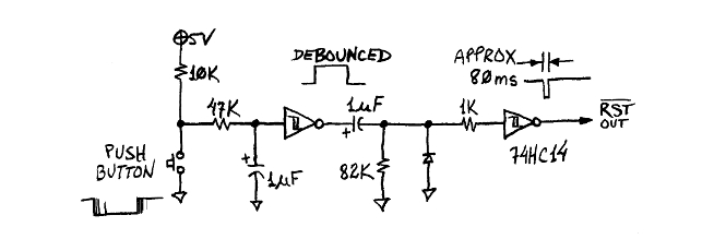
- Your reset circuit is insufficient for use with the WDC 65C02. The WDC C02’s reset input is not Schmitt-triggered—you will not get a clean reset with what you have. I suggest you use a Maxim DS1813 reset controller, or implement something like the reset circuit shown on Garth’s website.
- SO on the MPU is floating. SO is an input and must be terminated, usually by being connected to VCC. Left floating, noise pickup on SO could cause the V bit in the status register to randomly set, triggering possible errors in sections of code that use the BVC or BVS instructions.
As the others noted, a system constructed on a solderless breadboard is often a hit-and-miss affair. Your unit could be wired exactly to design and still be unstable or DOA due to reactive effects associated with those long, curving wires. Also, with the bypass capacitors so far away from the chips, I doubt they are doing anything for you. That, and you need to get the oscillator a lot closer to everything so the signal that arrives at the chips has a vague resemblance to the signal leaving the oscillator.
x86? We ain't got no x86. We don't NEED no stinking x86!
Re: LCD Text jumbled on 6502
Thanks for all the help everyone! I was worried it might be a wiring problem, but I guess I'll go triple-check everything again. I'll also make sure to tie that floating input to 5v.
Re: LCD Text jumbled on 6502
It might be a wiring problem, but I hope you've duly considered Garth's remarks re writing the function set three times... ie; a software problem. And have you no comment about the damage I mentioned to the LCD assembly?
Of course I can't know for certain what's going on, but to me it's entirely plausible that all your wiring is correct and the computer is working properly... but the message is becoming garbled after it is received by the LCD assembly. Garth's theory could explain this, as could mine.
If the problem is due to the mechanical damage, you'd need to either test the existing display in another computer, or (better yet) get a new display to test in the existing computer.
-- Jeff
In 1988 my 65C02 got six new registers and 44 new full-speed instructions!
https://laughtonelectronics.com/Arcana/ ... mmary.html
https://laughtonelectronics.com/Arcana/ ... mmary.html
Re: LCD Text jumbled on 6502
Jeff, I think that might just be a photo artifact and not a drilled hole. Looks like maybe the backlight is bleeding? Doesn't mean that the LCD isn't the culprit, though! Maybe it's loose.
besser435, you're building a known-working design to run known-working code. That makes your troubleshooting easier, in a way. Either the problem is hardware failure - you've received some component that is defective (pretty unlikely, but not impossible) - or you made a mistake somewhere along the way (much more likely). It's hard to diagnose a mistake from a photo of a breadboard build that doesn't look much different from (actually, it looks nicer than many of) the literally hundreds of other photos of the same kit floating around on Reddit.
The experts who are telling you not to leave CMOS input pins floating and that you need more bypass capacitors are totally right; you should read those links and learn about parasitic capacitance. What's more, it's an easy fix. Adding a bypass cap and a ground return loop to each chip will probably take less than 5 minutes. It might even fix your problem! But I doubt it; Ben's kits usually work in spite of cutting some corners on best practices.
What kind of troubleshooting have you already done? Do you have a digital multimeter? I use this one:
https://www.amazon.com/ANENG-AN8008-Mul ... B076GZK62B
It is not too expensive, and is adequate for a hobbyist. It has a square-wave sense mode, so you can use it to check of your oscillator is working. (It won't tell you how clean your clock signal is, though.) What about the Arduino bus monitor; do you have that? Did you buy a commercial EEPROM programmer, or did you build one? (Or did the EEPROM come pre-programmed?)
I suspect that, since you don't have the clock module, that you've jumped straight into building the final kit, without building along with the videos, step-by-step. I think that might not be the best approach. I'm going to suggest you take a short break from your breadboard 6502 and build a clock module. Not necessarily the one in Ben's kit (read the Primer page on clocking the 6502 for more options) but a 555-timer circuit is an easy and cheap one to make. Take the trouble to really understand how it works! Engage with the circuit; try different resistor and capacitor values and see if you get the pulses you expect. Learn about the bistable and monostable modes of the 555-timer as well. If the output of your timer isn't symmetrical, do you know how to make it symmetrical? A plain 555-timer clock does drive the WDC 65C02, but it's technically not in spec (the rise/fall times are too slow). Do you know how to make them faster? The answer is in Ben's videos, but not always obvious, or delivered directly. (Hint: the secret to cleaning up your clock signal is disclosed in the PS/2 keyboard videos.)
Once you've armed yourself with better tools and better knowledge, you might just try rebuilding the whole kit, one step at a time, verifying as you go. If you take the "isolate and simplify" approach, when something does go wrong you'll have already eliminated many possible explanations. Of course, you should still re-check your previous steps. Just because your address bus was working last step doesn't mean that something hasn't come loose now! But if you know not just where each wire goes but *why* it goes there, what it's for, what it does when it's hooked up right, and what happens when it isn't, then each step will build your confidence and help focus your attention in the right direction when things don't work as expected.
"The key is not to let the hardware sense any fear." - Radical Brad
Re: LCD Text jumbled on 6502
Paganini wrote:
Jeff, I think that might just be a photo artifact and not a drilled hole. Looks like maybe the backlight is bleeding? Doesn't mean that the LCD isn't the culprit, though! Maybe it's loose.
besser435, you're building a known-working design to run known-working code. That makes your troubleshooting easier, in a way. Either the problem is hardware failure - you've received some component that is defective (pretty unlikely, but not impossible) - or you made a mistake somewhere along the way (much more likely). It's hard to diagnose a mistake from a photo of a breadboard build that doesn't look much different from (actually, it looks nicer than many of) the literally hundreds of other photos of the same kit floating around on Reddit.
The experts who are telling you not to leave CMOS input pins floating and that you need more bypass capacitors are totally right; you should read those links and learn about parasitic capacitance. What's more, it's an easy fix. Adding a bypass cap and a ground return loop to each chip will probably take less than 5 minutes. It might even fix your problem! But I doubt it; Ben's kits usually work in spite of cutting some corners on best practices.
What kind of troubleshooting have you already done? Do you have a digital multimeter? I use this one:
https://www.amazon.com/ANENG-AN8008-Mul ... B076GZK62B
It is not too expensive, and is adequate for a hobbyist. It has a square-wave sense mode, so you can use it to check of your oscillator is working. (It won't tell you how clean your clock signal is, though.) What about the Arduino bus monitor; do you have that? Did you buy a commercial EEPROM programmer, or did you build one? (Or did the EEPROM come pre-programmed?)
I suspect that, since you don't have the clock module, that you've jumped straight into building the final kit, without building along with the videos, step-by-step. I think that might not be the best approach. I'm going to suggest you take a short break from your breadboard 6502 and build a clock module. Not necessarily the one in Ben's kit (read the Primer page on clocking the 6502 for more options) but a 555-timer circuit is an easy and cheap one to make. Take the trouble to really understand how it works! Engage with the circuit; try different resistor and capacitor values and see if you get the pulses you expect. Learn about the bistable and monostable modes of the 555-timer as well. If the output of your timer isn't symmetrical, do you know how to make it symmetrical? A plain 555-timer clock does drive the WDC 65C02, but it's technically not in spec (the rise/fall times are too slow). Do you know how to make them faster? The answer is in Ben's videos, but not always obvious, or delivered directly. (Hint: the secret to cleaning up your clock signal is disclosed in the PS/2 keyboard videos.)
Once you've armed yourself with better tools and better knowledge, you might just try rebuilding the whole kit, one step at a time, verifying as you go. If you take the "isolate and simplify" approach, when something does go wrong you'll have already eliminated many possible explanations. Of course, you should still re-check your previous steps. Just because your address bus was working last step doesn't mean that something hasn't come loose now! But if you know not just where each wire goes but *why* it goes there, what it's for, what it does when it's hooked up right, and what happens when it isn't, then each step will build your confidence and help focus your attention in the right direction when things don't work as expected.
besser435, you're building a known-working design to run known-working code. That makes your troubleshooting easier, in a way. Either the problem is hardware failure - you've received some component that is defective (pretty unlikely, but not impossible) - or you made a mistake somewhere along the way (much more likely). It's hard to diagnose a mistake from a photo of a breadboard build that doesn't look much different from (actually, it looks nicer than many of) the literally hundreds of other photos of the same kit floating around on Reddit.
The experts who are telling you not to leave CMOS input pins floating and that you need more bypass capacitors are totally right; you should read those links and learn about parasitic capacitance. What's more, it's an easy fix. Adding a bypass cap and a ground return loop to each chip will probably take less than 5 minutes. It might even fix your problem! But I doubt it; Ben's kits usually work in spite of cutting some corners on best practices.
What kind of troubleshooting have you already done? Do you have a digital multimeter? I use this one:
https://www.amazon.com/ANENG-AN8008-Mul ... B076GZK62B
It is not too expensive, and is adequate for a hobbyist. It has a square-wave sense mode, so you can use it to check of your oscillator is working. (It won't tell you how clean your clock signal is, though.) What about the Arduino bus monitor; do you have that? Did you buy a commercial EEPROM programmer, or did you build one? (Or did the EEPROM come pre-programmed?)
I suspect that, since you don't have the clock module, that you've jumped straight into building the final kit, without building along with the videos, step-by-step. I think that might not be the best approach. I'm going to suggest you take a short break from your breadboard 6502 and build a clock module. Not necessarily the one in Ben's kit (read the Primer page on clocking the 6502 for more options) but a 555-timer circuit is an easy and cheap one to make. Take the trouble to really understand how it works! Engage with the circuit; try different resistor and capacitor values and see if you get the pulses you expect. Learn about the bistable and monostable modes of the 555-timer as well. If the output of your timer isn't symmetrical, do you know how to make it symmetrical? A plain 555-timer clock does drive the WDC 65C02, but it's technically not in spec (the rise/fall times are too slow). Do you know how to make them faster? The answer is in Ben's videos, but not always obvious, or delivered directly. (Hint: the secret to cleaning up your clock signal is disclosed in the PS/2 keyboard videos.)
Once you've armed yourself with better tools and better knowledge, you might just try rebuilding the whole kit, one step at a time, verifying as you go. If you take the "isolate and simplify" approach, when something does go wrong you'll have already eliminated many possible explanations. Of course, you should still re-check your previous steps. Just because your address bus was working last step doesn't mean that something hasn't come loose now! But if you know not just where each wire goes but *why* it goes there, what it's for, what it does when it's hooked up right, and what happens when it isn't, then each step will build your confidence and help focus your attention in the right direction when things don't work as expected.
Re: LCD Text jumbled on 6502
Paganini wrote:
Jeff, I think that might just be a photo artifact and not a drilled hole.
Paganini wrote:
... a known-working design to run known-working code.
I don't know whether Ben's code obeys this protocol, but I can believe it might not. I'm aware that others have successfully used his code. However, their success may be due to the controller in the LCD module being from a different manufacturer.
The fact that besser435's LCD produces any message at all tells me that the project is 95% working. Re the one remaining glitch, I tend to favor theories that pertain directly to the LCD, and I give less credence to theories about something like the address or data bus (which usually send the entire computer into the weeds).
-- Jeff
Last edited by Dr Jefyll on Thu Dec 15, 2022 9:00 pm, edited 1 time in total.
In 1988 my 65C02 got six new registers and 44 new full-speed instructions!
https://laughtonelectronics.com/Arcana/ ... mmary.html
https://laughtonelectronics.com/Arcana/ ... mmary.html
Re: LCD Text jumbled on 6502
Dr Jefyll wrote:
Paganini wrote:
Jeff, I think that might just be a photo artifact and not a drilled hole.
Dr Jefyll wrote:
According to Garth, "a reliable reset and setup requires writing the function set three times as shown there; and if you don't do that, you can sometimes get problems like you're talking about."
I don't know whether Ben's code obeys this protocol, but I can believe it might not. I'm aware that others have successfully used his code. However, their success may be due to the controller in the LCD module being from a different manufacturer.
The fact that besser435's LCD produces any message at all tells me that the project is 95% working. Re the one remaining glitch, I tend to favor theories that pertain directly to the LCD, and I tend to give less credence to theories about something like the address or data bus (which usually send the entire computer into the weeds).
"The key is not to let the hardware sense any fear." - Radical Brad