Hi,
Hope this is not presumptuous for a newbie...
I have been laser cutting some 4004 dies into acrylic (just for fun) and was thinking of doing the same for a 6502. I had a look at the visual6502 simulator but the vector files seem to be embedded in a javascript file. Does anyone know where I can source them is some other format?
I am happy to give a laser cut 6502 to anyone who helps (and assuming that I can actually get the cut done).
See the attached 4004 - this is cut in 3 layers - metal, poly and diffusion - it does not include vias - might get round to adding these in the future. This was from some die shots off the 4004 web site which I vectorised using Corel trace - this approach will not work for the 6502 as the files end up too big.
Thanks
6502 Vector image
-
chrissmith
- Posts: 14
- Joined: 05 Mar 2017
- Location: Sydney, Australia
6502 Vector image
- Attachments
-
-
BigDumbDinosaur

- Posts: 9428
- Joined: 28 May 2009
- Location: Midwestern USA (JB Pritzker’s dystopia)
- Contact:
Re: 6502 Vector image
chrissmith wrote:
I have been laser cutting some 4004 dies into acrylic (just for fun) and was thinking of doing the same for a 6502.
x86? We ain't got no x86. We don't NEED no stinking x86!

Re: 6502 Vector image
Neat idea!
Maybe the SVG version of 6502 will be a good starting point?
https://github.com/BigEd/visual6502/tree/gh-pages
(visible at http://biged.github.io/visual6502/)
(Any thoughts on using pale-coloured stock?)
Maybe the SVG version of 6502 will be a good starting point?
https://github.com/BigEd/visual6502/tree/gh-pages
(visible at http://biged.github.io/visual6502/)
(Any thoughts on using pale-coloured stock?)
-
chrissmith
- Posts: 14
- Joined: 05 Mar 2017
- Location: Sydney, Australia
Re: 6502 Vector image
That look exactly like what I want - do not have autocad at work so will run it up when I get home - should cut OK.
I am surprised that the transistor count of the 6502 is 3510 vs 2300 for the 4004 - would expect it to be higher.
Not sure what you mean by pale coloured stock? - it is not obvious from the pic but there dies are cut on 3 separate layers and then you can see them align when you look through - needs to be clear for that to work.
Re: 6502 Vector image
Hope the svg does work out! Inkscape is another viewer.
By pale coloured stock, I mean using coloured acrylic so the layers have colours, and they overlap like they do in silicon. Just an idea!
On the subject of transistor counts, I found this: "The 6502 chip is made up of 4528 transistors (3510 enhancement transistors and 1018 depletion pullup transistors)." The visual6502 does model both, but the obvious ones are the pulldowns and the count of pulldowns is the number which tends to be prominent.
-
chrissmith
- Posts: 14
- Joined: 05 Mar 2017
- Location: Sydney, Australia
Re: 6502 Vector image
I need to run it through autocad to clean it up and separate out the layers for the laser cutter - should only be 2x as complicated as the 4004 so hopefully will cut OK. Will try to get it done tonight (Australia time) and post some photos tomorrow.
-
BigDumbDinosaur
- Posts: 9428
- Joined: 28 May 2009
- Location: Midwestern USA (JB Pritzker’s dystopia)
- Contact:
Re: 6502 Vector image
chrissmith wrote:
I am surprised that the transistor count of the 6502 is 3510 vs 2300 for the 4004 - would expect it to be higher.
Quote:
Not sure what you mean by pale coloured stock? - it is not obvious from the pic but there dies are cut on 3 separate layers and then you can see them align when you look through - needs to be clear for that to work.
x86? We ain't got no x86. We don't NEED no stinking x86!
-
chrissmith
- Posts: 14
- Joined: 05 Mar 2017
- Location: Sydney, Australia
Re: 6502 Vector image
Actually lighting is what I do - this was just a quick side project to test out what the laser could cut.
https://www.facebook.com/The-Light-Work ... 776687388/
So yes I will probably try a side lit version of this, have all the bit I need in the shed including a whole lot of WS2812B addressable LED strip, maybe run up a 6502 based lighting controller...
https://www.facebook.com/The-Light-Work ... 776687388/
So yes I will probably try a side lit version of this, have all the bit I need in the shed including a whole lot of WS2812B addressable LED strip, maybe run up a 6502 based lighting controller...
Re: 6502 Vector image
Side lit with RGB LEDs is a good idea!
-
arduinoenigma

- Posts: 9
- Joined: 12 Dec 2016
- Contact:
Re: 6502 Vector image
Really beautiful. Just what kind of materials does a laser-thingie like that do? I had my MacBook lasered at the time (expensive, but well worth it), so I know about that aluminum stuff.
-
chrissmith
- Posts: 14
- Joined: 05 Mar 2017
- Location: Sydney, Australia
Re: 6502 Vector image
So thanks to BigEd located the SVG file but could not get it to convert to DXF to load into autocad - the converted file just errored and crashed my ancient Autocad. 2nd approach was to load up inkscape (again thanks BigEd) and use inkscape to separate out the layers and save them out as DXF - this took a while to understand the pitfalls of the inkscape dxf export (it only woks with ungrouped paths). This was moderately successful, lots of application crashes and 15min waits while it resized images but I now have a set of DXF files with the correctly sized (150 x 150 mm). Maybe I need to upgrade my shed computer or maybe it just doesn't like doing the 6502 when it comes from the 4004-8080-8086 family.
It is interesting that though the transistor count of the 6502 is only around 2x that of the 4004 (2300 vs 4528) the files are about 10x as big (11mb just for the poly layer) and they look correspondingly complex.
It is a pity there is no branding or any other information on the die - I like the fact that Federico Faggin put his intials on the 4004 and there is a nice funky Intel 71 logo.
I purchased my laser cutter to work with folded polypropylene for the line of lamps I make but have found it cuts acrylic beautifully. Have also cut wood (but lots of burn marks on the edge). I will mark but not cut metal - you need more power and oxygen assist for that. Its a 60w no name Chinese machine but has been great to work with.
Re: 6502 Vector image
Glad you managed to get something from the SVG - sorry it was a bit of a pain. Possibly one reason for the size is that many small jogs in the layout are in there, where they could possibly have been smoothed out. Maybe the 4004 is smoothed, maybe the layout didn't have the jogs.
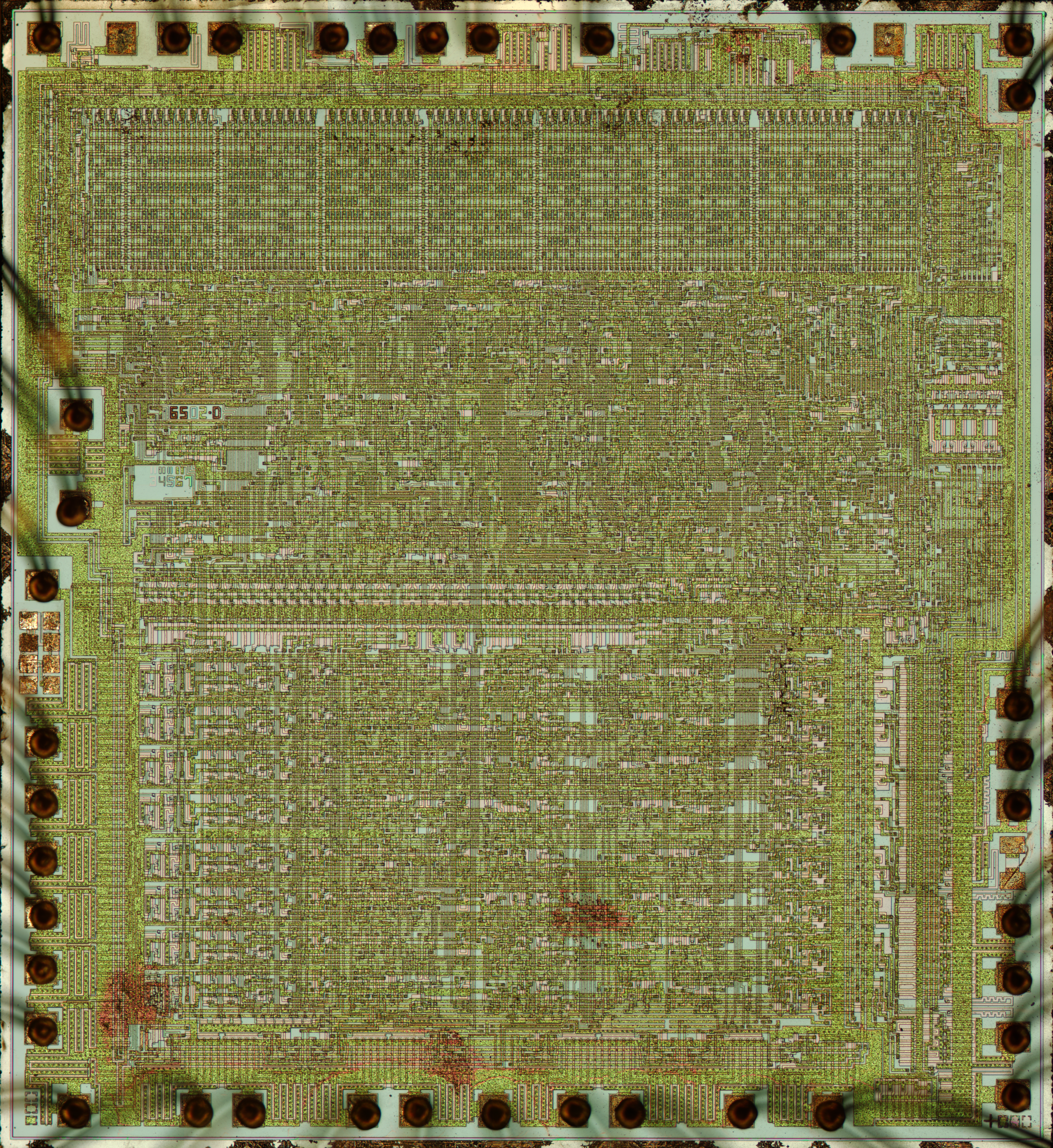
There is a little branding on the 6502, perhaps you'd be able to recreate it in vector form. There's a 6502D on the visual6502 one: huge huge image here
http://visual6502.org/images/6502/6502_ ... F_4677.png
and see the attached closeup.
I'm pretty sure some 6502 chips have an "MOS" on them. There are lots of chips at
https://commons.wikimedia.org/wiki/User:Birdman86
but his 6502 seems to be a 6502A without "MOS". (Actually, knowing where to look, it is there - left end of the top edge. See below. So we can also find it on the Visual 6502 image now, at top end of the right edge - see attached.)
Ah, here it is - see second attachment - from this large image
http://archive.computerhistory.org/reso ... 631294.jpg
- Attachments
-
-
-
-
chrissmith
- Posts: 14
- Joined: 05 Mar 2017
- Location: Sydney, Australia
Re: 6502 Vector image
It looks like the branding was removed from the SVG image - its certainly not there in the emulator - will have a look at the layers when I get home.
It looks like the original die had different letters of 6502.D on different layers. Should not be too difficult to vector it from the image and drop it back in the DXF. Should be legible in the laser cut even though it is small. Looks like there is also a test pattern (34567) below which is missing from the SVG - will add that back in too.
It looks like the original die had different letters of 6502.D on different layers. Should not be too difficult to vector it from the image and drop it back in the DXF. Should be legible in the laser cut even though it is small. Looks like there is also a test pattern (34567) below which is missing from the SVG - will add that back in too.
Re: 6502 Vector image
Yes, I suspect the visual6502 team only traced the polygons which were functional - or, they dropped unconnected polygons at some point. The different colours of the 3 4 5 6 7 will help determine which layers are which elsewhere, if it's ambiguous. I would guess the "MOS" letters are in poly. Probably layer 4? Then 5 would be contact cut, 6 metal and 7 overglass.