Challenge : The Most Minimal Breadboard 6502 Video Computer.

For discussing the 65xx hardware itself or electronics projects.
User avatar
Hobbit1972
Posts: 80
Joined: 10 Feb 2015
Location: Germany

Re: Challenge : The Most Minimal Breadboard 6502 Video Compu

Post by Hobbit1972 »

Oneironaut wrote:
All good questions!
...
Yes, video needs to be at least capable of a text that is readable on the screen!
Thanks for clarification. So nice graphics would not be enough, some discernable text is mandatory? (I thought about some nice Lissajous graphs :mrgreen: )

Allowing for a microcontroller/... seems a bit... odd to me...


Sound: feeding an appropriate adress line into a speaker generating a fixed square wave would be it?
User avatar
Arlet
Posts: 2353
Joined: 16 Nov 2010
Location: Gouda, The Netherlands
Contact:

Re: Challenge : The Most Minimal Breadboard 6502 Video Compu

Post by Arlet »

Quote:
Allowing for a microcontroller/... seems a bit... odd to me...
Agreed, especially since it's been done many times already, and doesn't even need a 6502, so it can be done with a single chip.

Here's a nice one done by Linus Åkesson 8 years ago.
User avatar
Michael
Posts: 633
Joined: 13 Feb 2013
Location: Michigan, USA

Re: Challenge : The Most Minimal Breadboard 6502 Video Compu

Post by Michael »

Oneironaut wrote:
You read my mind!
I am actually shooting for a 2 chip system. one 65C02 and one AVR1284.
Fantastic! Can't wait to see what you come up with. I've got a couple ATMEGA1284P-PU chips waiting (grin)...

Happy Holidays... Cheerful regards, Mike
Klaus2m5
Posts: 442
Joined: 28 Jul 2012
Location: Wiesbaden, Germany

Re: Challenge : The Most Minimal Breadboard 6502 Video Compu

Post by Klaus2m5 »

So if one can do it with 2 chips and one has to be a 6502 of some sort, why bother to enter the challenge? Nobody can do it with less. If performance would count it would be a different story.
Last edited by Klaus2m5 on Sat Dec 24, 2016 1:31 pm, edited 1 time in total.
6502 sources on GitHub: https://github.com/Klaus2m5
Martin A
Posts: 197
Joined: 02 Jan 2016

Re: Challenge : The Most Minimal Breadboard 6502 Video Compu

Post by Martin A »

How about using a PLD as both boot ROM and chip select logic.

As a proof of concept, I managed to squeeze 49 bytes of rom into a 22V10. That used 6 inputs for the address bus (blue), one each for chip select and output enable (green) and 8 outputs for data (yellow). That leaves 2 more I/O pins and 4 inputs for more normal logic functions.
49 bytes of "rom" in a GAL
49 byte ROM.jpg (41.16 KiB) Viewed 2244 times
The proof of concept rom happens to be a minimalist IDE/CF boot loader in Z80 code. I don't know enough about 6502 hardware and software to know if a boot loader can be made small enough and the hardware simple enough to do something similar.

Possible though ??
User avatar
Oneironaut
Posts: 734
Joined: 25 May 2015
Location: Gillies, Ontario, Canada
Contact:

Re: Challenge : The Most Minimal Breadboard 6502 Video Compu

Post by Oneironaut »

Let me clarify some of the rules I have set for myself and the reason...

This is all about chip breadboard count, and nothing else.
Imagine being a noob, and only needing to drop down 2 chips.... nice way to begin!

My goal : 10 minutes of work for under $50.00, and you are now coding a real 6502.
You soon see your code come to life in sound and video. No ROMs!

Anyhow, this is a personal challenge, I just wanted to open it up to everyone for fun.

Oh, and about the video... text or graphics.
If a 16x16 pixel display and one tone beeper is all you need to enjoy coding, than that's just fine.


I wasn't going to post anything until the project was at least proven, but I have made some progress...

Image
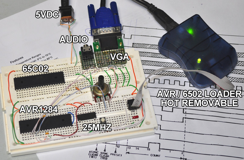
The goal is to make this into a working 6502 Audio / Video Computer!

What is shown above will have nothing else but wires attached from this point on.
The AVR has 128K of Flash Memory and 16K of fast SRAM.
The 6502 will get most of the SRAM for variables, and about 40K for ROM code.
Pins are scarce, so I may only get mono color text and one channel sound.

I have done some very basic video code for the AVR, and although ugly, it does show text...

Image
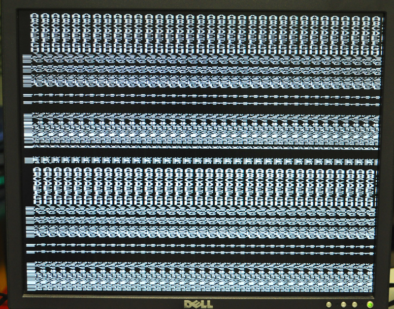
This is a 320x480 pixel display over the 640x480 VGA Standard.

Once I clean up the Text Generator, it will be capable of showing 38 x 60 characters.
I have one more test to do that may bring this up to 40 x 60 characters.
Depending on how the 65C02 agrees with fast tri-stating, I may be able to get 64 colors as well!
Sound will be 2 or 4 mixed voices coming out as a mono signal. Music will certainly be possible.

But the ultimate goal of "Easy to Start with 6502" will be met.
That AVR programmer is under twenty bucks, and the AVR is only 10 bucks.
I wrote a BIN converter so that any 6502 assembler can be used (I am using the Kowalski Assembler).
Once you load through the AVR Programmer, it can be pulled right out... this is a fully stand alone 6502 computer.
The AVR is simply a fancy SRAM & ROM with a built in VGA, Sound, and Clock Generator.

If an FPGA / CPLD exists in DIP form, then for sure someone will blow my version away!
And yes, a faster more colorful 2 chip system would be the winner.
And no soldering down of SMD onto DIP adapters allowed this time... it's all about making it easy for anyone to start!

I will be posting the AVR code, and the Assembler Bridge program as soon as this is ready.
An AVR + Programmer can be purchased at just about any electronics supplier.
the 65C02 can be purchased at the Western Design Center.
I will also add the BOM for the connectors and crystal... all are inexpensive as well.

Good to go!
Brad
Martin_H
Posts: 837
Joined: 08 Jan 2014

Re: Challenge : The Most Minimal Breadboard 6502 Video Compu

Post by Martin_H »

Klaus2m5 wrote:
So if one can do it with 2 chips and one has to be a 6502 of some sort, why bother to enter the challenge? Nobody can do it with less. If performance would count it would be a different story.
This ties into the retro computer purity discuss. Over reliance on a modern microcontroller reduces the exercise into an emulation project, and at that point your might as well emulate the 6502 as well.

It would be more interesting to me to reduce the glue logic to a single chip (e.g. Daryl's memory decoder GAL http://sbc.rictor.org/decoder.html), and then focus on a way to generate video using the 6502 itself. But it's also beyond my ability at present.
User avatar
Oneironaut
Posts: 734
Joined: 25 May 2015
Location: Gillies, Ontario, Canada
Contact:

Re: Challenge : The Most Minimal Breadboard 6502 Video Compu

Post by Oneironaut »

If the AVR version fails, then my fall-back plan is to use the 6502 to generate video directly.
I have a design that uses a few counters and a latch in order to get 256 x 240 mono bitmapped graphics.
The counter would rollover and the carry pin would act as an external interrupt for the 6502.
At that point, the 6502 would draw a horizontal line and finish with a sync pulse.
I figured on 8-10 chips (a 65C02, one 32k SRAM, and 4-6 logic chips). Loading would be serial port.

On my drive home last night, I realized that an AVR could replicate what I did on the Fusion project (FPGA).
By varying the 6502 clock duty cycle, it was possible to get much more performance than with a 50% duty clock.

If my current 2 chip plan works (and that's a big if), then i will basically have a PET4032 made with 2 chips on a breadboard.
Seems the main daunting issue with most that would ever consider a real (non emulated) 6502 is the initial prototype.
Hopefully, this project will obliterate that problem.

How about I make boards and call it... Sixty-Five-Oh-Duino-Retros-Millo-Doover-Moreoh-Deci-Digi-Cumulator-Kernalmov??
That's Italian for : I am afraid of a breadboard so I will pay too much for a cheap 6502 PCB.

... I know -> shoot me now please! I am still hurting from last night's Jack Daniels overflow.

Ok, back to counting cycles in AVR assembly so I can bring up 6502 assembly on screen.
Brad
sark02
Posts: 241
Joined: 10 Nov 2015

Re: Challenge : The Most Minimal Breadboard 6502 Video Compu

Post by sark02 »

Arlet wrote:
Here's a [single chip computer] nice one done by Linus Åkesson 8 years ago.
That's insane. It reminds me of the Atari ST demo scene from the 90s, and what those teams (mostly European) could make the machines do. Saying it's "very impressive" isn't even beginning to do it justice.
sark02
Posts: 241
Joined: 10 Nov 2015

Re: Challenge : The Most Minimal Breadboard 6502 Video Compu

Post by sark02 »

Martin_H wrote:
This ties into the retro computer purity discuss.
It does. They're his rules to make, of course, but if retro/nostalgia are elements then I can think of four levels:
  1. a) Era accurate
  1. b) Bus accurate
  1. c) Cycle accurate
  1. d) Instruction accurate
"Era accurate" would mean a standard WDC 65C02 surrounded by discrete 7400 chips, RAMs and EEPROMs. Building a little computer as you would have done if you were playing with this stuff in the late 70s / early 80s. A practical concession would be to permit modern SRAMs/flash.

"Bus accurate" would mean a standard WDC 65C02, and therefore it's real bus model, but surrounded by whatever modern tech you like. The goal would be to build a machine around an authentic 6502, but with the utility of modern design elements (microcontrollers and FPGAs).

"Cycle accurate" would mean instruction-level accuracy where instructions take the correct number of cycles to execute, including RDY effects, if appropriate. An FPGA emulation would work here, as would a software emulator. The goal would be to be able to emulate a real world design, only implemented without constraints. From a software perspective, it would allow you to write and test 6502 algorithms with accurate timing (my square root is faster than your square root).

"Instruction accurate" means that the 6502 instruction set is faithfully modeled in its execution, with no constraints on cycle times or bus model. This would be for working with the 6502 instruction set, either with an FPGA or emulator, without regard for cycle accuracy.

I'm sure there are other classifications, but these are the ones that immediately come to mind.

My interest in the 6502 generally hits the last two, playing with the 6502 either with an old computer emulator (cycle accurate) or just a simple ISA emulator (instruction accurate).

This sounds like a "bus accurate" challenge.
User avatar
Oneironaut
Posts: 734
Joined: 25 May 2015
Location: Gillies, Ontario, Canada
Contact:

Re: Challenge : The Most Minimal Breadboard 6502 Video Compu

Post by Oneironaut »

Just to steer this back in the right direction...

This is ONLY about dropping a REAL 6502 DIP into a breadboard and getting the most minimal "computer" possible.
By computer, I mean something capable of displaying video and sound to readily available media appliances.

It also needs to be extremely easy to program for fun and rapid hacking / learning.

Right now, I am trying to make my 2 chip 6502 system work.
It can be programmed using any PC and any windows based 6502 assembler.
It can be built for under fifty bucks on a breadboard by anyone that can chew bubblegum.
You can write 6502 code, and see the results of our work on screen within 5 seconds of compile.

This is what I am trying to capture.
I am 50% there now.
Someone good with a PIC32 or LPCARM DIP could most likely do much better!

Brad
User avatar
Oneironaut
Posts: 734
Joined: 25 May 2015
Location: Gillies, Ontario, Canada
Contact:

Re: Challenge : The Most Minimal Breadboard 6502 Video Compu

Post by Oneironaut »

Ok, the code needs some optimization, but I have a 36x60 monochrome display up and running.
Using the crippled SPI in the AVR, I could not achieve a 40 character display because it requires 9 cycles per byte!

I am going to try adding one more chip (75HC574) in order to get a 256 color display. It seems worth it.
That would allow each character to be any one of 256 colors.
With the extra chip, the system could also have a 160x120 16 color full bitmap mode.

Ok, more testing to see what happens!

Brad
User avatar
8BIT
Posts: 1787
Joined: 30 Aug 2002
Location: Sacramento, CA
Contact:

Re: Challenge : The Most Minimal Breadboard 6502 Video Compu

Post by 8BIT »

Use the USART in SPI mode and you can generate 40 character displays. I've done a 320x200 monochrome display using the ATMega1284. Since there are two USARTS, you can still have a serial console port too.

Daryl
Please visit my website -> https://sbc.rictor.org/
User avatar
Oneironaut
Posts: 734
Joined: 25 May 2015
Location: Gillies, Ontario, Canada
Contact:

Re: Challenge : The Most Minimal Breadboard 6502 Video Compu

Post by Oneironaut »

Thanks, I was actually just trying to make that work as you responded!
So far, I did get 40 characters, but the SPI seems to send a HI on the TX pin when it is done.
I have tried disabling the SPI and re-enabling at the start of the line, but there is still a rouge pixel.

I have tried every possible combination of modes, but can't get the SPI to invert.
If I could, I would just invert my character ROM and live with that.

I may just control the OE on an external latch and then also use it to gain some color.

I can shave another cycle from my 16 clock loop here, but this is how I do the 40 characters now...

Code: Select all

ld r17,X+ ;2
ldi ZL,lo8(CHARS) ;1
ldi ZH,hi8(CHARS) ;1
mul r18,r17 ;2
add ZL,r0 ;1
adc ZH,r1 ;1
add ZL,r19 ;1
clr r0 ;1
adc ZH,r0 ;1
elpm r17,Z ;3
sts UDR1,r17 ;2
USART is set to SPI at SCLK /2.
Still trying to ditch that inverted idle state somehow in code.

Brad
8BIT wrote:
Use the USART in SPI mode and you can generate 40 character displays. I've done a 320x200 monochrome display using the ATMega1284. Since there are two USARTS, you can still have a serial console port too.
Daryl
User avatar
8BIT
Posts: 1787
Joined: 30 Aug 2002
Location: Sacramento, CA
Contact:

Re: Challenge : The Most Minimal Breadboard 6502 Video Compu

Post by 8BIT »

I think what I did was to write a 41st byte that was 0x00 to keep the data pin to stay low until it ran off of the right edge.

Also, I enable to USART and immediately write 0x00 to the UDR register before I start sending characters to keep the left edge low as well. So in actuality, I'm writing 42 bytes per line.

Hope that helps.

Daryl

Here is my code for that section

Code: Select all


; init pointers to character data in RAM and then do this code:

	LDI		XH, 0x00
	ldi 	xl, (0<<RXEN1)|(1<<TXEN1)
	sts		udr1, xh			; 2   send 0x00 to SPI, (USART is disabled)
	sts 	UCSR1B,	xl                     ; 2  USART is enabled
	sts		udr1, xh			; 2   send 0x00 to SPI (USART is enabled)

	lpm		xl, Z				; 3   nop
	lpm		xl, Z				; 3   nop
	lpm		xl, Z				; 3   nop
	lpm		xl, Z				; 3   nop
	lpm		xl, Z				; 3   nop
	movw	xl, acc			; 1
	lds		acch, mnumbytes	; 2

BUILDSCREEN:                                  ; repeat this 40 times
	lds		acc, ucsr1a		; 2   read SPI status 
	ld 		acc, X+			; 2   move curr chr in ZL
	sts		udr1, acc			; 2   send to SPI

	lpm		xl, Z				; 3   nop
	lpm		xl, Z				; 3   nop
	nop						; 1
	dec		acch				; 1
	brne	BUILDSCREEN			; 2/1
	
	ldi		xl, 0x00			; 1	
	sts		udr1, xl			; 2 (only 12 clocks, because tx is buffered)
	sts 	UCSR1B,	xl			; 2 disable USART

end:
Last edited by 8BIT on Sun Dec 25, 2016 5:21 am, edited 1 time in total.
Please visit my website -> https://sbc.rictor.org/
Post Reply