6502.org Forum  Projects  Code  Documents  Tools  Forum
It is currently Thu Sep 19, 2024 10:28 pm

All times are UTC


Post new topic Reply to topic  [ 23 posts ]  Go to page Previous  1, 2
Author Message
PostPosted: Thu Jul 16, 2015 8:01 am 
Offline
User avatar

Joined: Thu Dec 11, 2008 1:28 pm
Posts: 10938
Location: England
I'm still wondering if it's the presence of TTL inputs which will drag down outputs, and so in a design without TTL inputs, the output levels will be higher than the minimum spec - and therefore within range of a weirdo spec.


Top
 Profile  
Reply with quote  
PostPosted: Thu Jul 16, 2015 8:30 am 
Offline

Joined: Sun Dec 28, 2014 11:04 pm
Posts: 82
Location: Munich, Germany
Dr Jefyll wrote:
ArnoldLayne wrote:
By checking the data lines with a scope, I see signal levels way beyond 3.5V, around 5V. So, yes, we happen to be within WDC spec after all, but not sure why, and not sure if that is always the case, with any device on the bus.
The data bus is bidirectional, so sometimes it'll be the WDC itself which drives it. That'd explain the 5V signal levels.

I checked the r/W line, too, so I know that I have seen mostly reads. Not really sure from where, though.

Dr Jefyll wrote:
If you haven't already, you could try syncing the scope to reads of that NMOS device you mentioned. It's when that device is driving the bus (and the WDC is supposed to receive the data) that we might have a problem with adequate voltage levels.


I'll take that as my homework for today.


Top
 Profile  
Reply with quote  
PostPosted: Thu Jul 16, 2015 2:14 pm 
Offline
User avatar

Joined: Fri Dec 11, 2009 3:50 pm
Posts: 3367
Location: Ontario, Canada
Quote:
I'll take that as my homework for today.
Sounds good. Btw, a reminder: if you're using an analog scope (not a DSO) and you're trying to scope something very specific -- in this case reads from the NMOS SRAM and from that TMS9929 -- it's very helpful to write a tiny loop that repeatedly performs the action you're trying to observe.

_________________
In 1988 my 65C02 got six new registers and 44 new full-speed instructions!
https://laughtonelectronics.com/Arcana/ ... mmary.html


Top
 Profile  
Reply with quote  
PostPosted: Sat Jul 18, 2015 7:17 am 
Offline

Joined: Sun Dec 28, 2014 11:04 pm
Posts: 82
Location: Munich, Germany
Okay,

I am late with my homework.
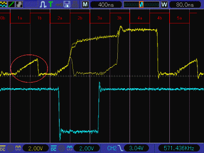
I wrote a small program that reads the TMS9929's status register in a tight loop. What we see on the screenshot is the TMS9929's /CSR-pin (blue curve) and the D2-line (yellow curve).
As we can see, the signal level when driven by that NMOS 9929 is just slighty above 4V, so apparently WDC safe.
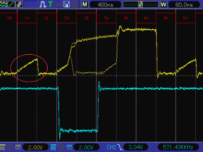
Using a 3.3k pullup resistor will pull up the level a bit (go figure..) but seems to pull up some noise, too.


Attachments:
File comment: Same, but using a 3.3k pullup resistor.
D2_VDP_3k3pullup.gif
D2_VDP_3k3pullup.gif [ 21.92 KiB | Viewed 1335 times ]
File comment: D2 signal level when bus driven by TMS9929
D2_VDP.gif
D2_VDP.gif [ 22.23 KiB | Viewed 1335 times ]
Top
 Profile  
Reply with quote  
PostPosted: Sat Jul 18, 2015 7:18 pm 
Offline
User avatar

Joined: Fri Dec 11, 2009 3:50 pm
Posts: 3367
Location: Ontario, Canada
OK, so in red I drew the Phase2 waveform in what I suppose to be the the correct relation, and I put the images in a two-frame animation, ie, with and without the pullup (below). It's no surprise to see that the pullup resistor has a distinct effect when Phase2 is low (for example in the first part of cycle 1, which I circled). This is entirely harmless. The 'C02 will always tri-state the data bus during Phase2 low, and ideally (but depending on its wiring) the host system will do the same. Hence there's nothing to prevent the pullup from pulling up.

The last half of cycle 2 seems strange, though. In the no-pullup frame we see the voltage drop sharply at the end (late in period 2b). Although it's slightly OT, I'm puzzled and bothered by this. It suggests something odd about the device, something odd about your wiring or the way the experiment was done, or something I'm missing or don't understand.

Just checking - you said the blue curve is the TMS9929's /CSR pin. Is that the device's chip-select input? Can you post or link to a datasheet for that chip? And did I get Phase2 in the correct relation to the other waveforms? Edit: alternative Phase2 interpretation added.

-- Jeff
Attachment:
Animation - effect of pullup resistor v1.gif
Animation - effect of pullup resistor v1.gif [ 25.97 KiB | Viewed 1287 times ]
Attachment:
Animation - effect of pullup resistor v2.gif
Animation - effect of pullup resistor v2.gif [ 26.29 KiB | Viewed 1287 times ]

_________________
In 1988 my 65C02 got six new registers and 44 new full-speed instructions!
https://laughtonelectronics.com/Arcana/ ... mmary.html


Last edited by Dr Jefyll on Sun Jul 19, 2015 2:57 pm, edited 2 times in total.

Top
 Profile  
Reply with quote  
PostPosted: Sun Jul 19, 2015 2:37 pm 
Offline
User avatar

Joined: Fri Dec 11, 2009 3:50 pm
Posts: 3367
Location: Ontario, Canada
In version 2 of the animation above I shifted the clock, and the result seems more plausible in some ways and less so in others.

I put two arbitrary timing marks in the excerpt below, both of which seem to indicate the effect of Phase2 going high (and output drivers being enabled). But they are not separated by an integer number of cycles; there's also a roughly one-quarter-cycle phase shift. Apparently there's one output driver that responds promptly to Phase2 going high, and another which for some reason is very sluggish to do so -- at least that's one possible explanation.


Attachments:
pullup excerpt.gif
pullup excerpt.gif [ 21.03 KiB | Viewed 1287 times ]

_________________
In 1988 my 65C02 got six new registers and 44 new full-speed instructions!
https://laughtonelectronics.com/Arcana/ ... mmary.html
Top
 Profile  
Reply with quote  
PostPosted: Thu Jul 23, 2015 1:29 pm 
Offline

Joined: Sun Dec 28, 2014 11:04 pm
Posts: 82
Location: Munich, Germany
Dr Jefyll wrote:
Just checking - you said the blue curve is the TMS9929's /CSR pin. Is that the device's chip-select input? Can you post or link to a datasheet for that chip? And did I get Phase2 in the correct relation to the other waveforms? Edit: alternative Phase2 interpretation added.


Hi,

the heat wave in Germany gives me a break today, so I'll try to clarify some stuff I should have been more specific about earlier.
First, here is the datasheet for the TMS9929. /CSR is the chip select input for reading, there is a separate one, /CSW, for writing.
http://www.datasheetarchive.com/dlmain/Datasheets-23/DSA-445645.pdf
Second, /CSR or /CSW are generated only from the address lines and r/W, there is no PHI2 involved.
I attached another graph to show how /CSR (yellow) relates to PHI2 (blue).


Attachments:
File comment: /CSR (yellow) and PHI2 (blue)
tekway286_2.gif
tekway286_2.gif [ 17.48 KiB | Viewed 1254 times ]
Top
 Profile  
Reply with quote  
PostPosted: Fri Dec 23, 2016 3:03 am 
Offline
User avatar

Joined: Fri Aug 30, 2002 1:09 am
Posts: 8509
Location: Southern California
I wrote above,
Quote:
WDC's data sheets have been rather bad over the years, fortunately on the bad side; ie, the parts perform much better than they say. The 2.4V output is to say that they can pull up at least that high with the specified load; but even there, they can pull up much, much higher. I have tested one I/O pin at a time of Rockwell's R65c22 and the WDC W65C22S outputs here (note the WDC ones having the "S" ending), and they are many times as strong as the data sheet says (and I believe the processor has the same output circuits). In my experiment, WDC's outputs were able to pull to within 0.8V of either rail with a 220-ohm resistor to the opposite rail, meaning a 19mA load, even pulling up, and give 50mA into a dead short. Rockwell's could pull down with 100mA into a dead short, but could not pull up as hard, not being symmetrical like WDC's.

At Jeff's prompting, I tested an '816 since I have a fixture set up for that, which I used in the recent half-cycling tests to figure out undocumented interrupt behavior. The data bus drivers appeared to be a little stronger than the address bus's. On the data bus, I could get valid CMOS levels (30% & 70%) at 30mA or better, both directions. For pulling down to .65V for a TTL low, I got 20mA. On the address bus, I was able to get valid CMOS logic levels at 21mA; and for pulling down to .59V, 10mA. (I was just trying different load resistors and recording the resulting voltages and calculating the currents.)

I tested only a few pins, of one IC, from one lot, and only at room temperature. I know it's not much, but it's all I'm willing to do at the moment for my project. I just wanted to confirm my suspicion, rather than do a full characterization as would be needed for a real data sheet. However, it does show that the pin drivers are a lot stronger than the WDC data sheet lets on. I should have done the same test for the W65C02S before I modified it for the '816; but I suspect they used the same pin-driver circuits for both processors.

If all loads are CMOS, our only interest in the current is to charge the capacitances, since holding a steady-state voltage does not require any current if the loads are all CMOS. Charging up a 25pF load by 4V takes 1ns @ 100mA average current over that nanosecond. For doing it in 4ns would require 25mA average over those 4ns.

The current won't be constant in practical situations though, nor will it follow the same curve you'd get in an RxC. It will be in between. The circuit can be approximated by a current-limiting mechanism plus a series resistance. On the address bus (which is not as strong as the data bus), the current at a pin when it has accomplished the first two volts of its journey from a high voltage to a low (or vice-versa) would be 43mA or a little more if the effects of inductance at the ground and Vcc connections could be reduced to negligible levels. If you had to go for a very rough number and treat it as just a resistance, the data-bus pins acted very roughly like a SPDT switch with 50Ω in series with the common terminal (ie, the output); and the address bus pins, as a SPDT switch with 60Ω in series.

_________________
http://WilsonMinesCo.com/ lots of 6502 resources
The "second front page" is http://wilsonminesco.com/links.html .
What's an additional VIA among friends, anyhow?


Top
 Profile  
Reply with quote  
Display posts from previous:  Sort by  
Post new topic Reply to topic  [ 23 posts ]  Go to page Previous  1, 2

All times are UTC


Who is online

Users browsing this forum: No registered users and 16 guests


You cannot post new topics in this forum
You cannot reply to topics in this forum
You cannot edit your posts in this forum
You cannot delete your posts in this forum
You cannot post attachments in this forum

Search for:
Jump to: