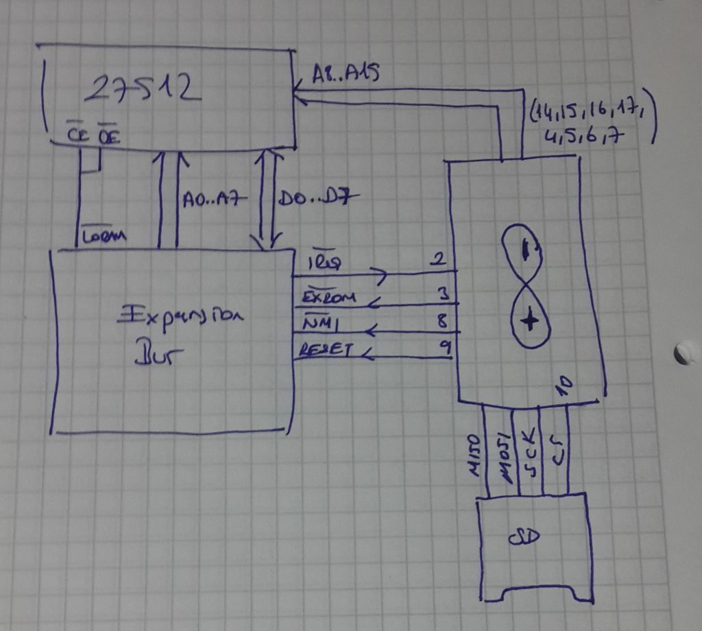
Jeff, I'm going over this topic again, thinking of my bootloader. I had forgotten about this topic when I emailed you the diagram showing the address lines connected to the µC. Getting rid of those, I can go down from a 40-pin µC to a 28-pin. (It's only a matter of board real estate though. I have all these sizes in stock.) The next one down is 18, which would be more than enough with what's in your last post above. The next size down is 8 pins, which is not enough, considering the outboard I²C EEPROM and a couple of other things needed for the '816.
I think I'm following most of what you wrote. The reason to use EA instead of A9 which would make it almost twice as fast just that A9 does not allow odd numbers of program-counter increments, right? 28->A9 still works with the resistor scheme. (For the 65c02, one of the single-cycle no-ops in columns 3 and B could be used.)
Next, is the idea just that you'd put just enough program material in page 1 to get the µP to run to get itself up the rest of the way?
Simple 3-Chip design Proof-of-Concept
-
GARTHWILSON

- Forum Moderator
- Posts: 8773
- Joined: 30 Aug 2002
- Location: Southern California
- Contact:
Re: Simple 3-Chip design Proof-of-Concept
http://WilsonMinesCo.com/ lots of 6502 resources
The "second front page" is http://wilsonminesco.com/links.html .
What's an additional VIA among friends, anyhow?
The "second front page" is http://wilsonminesco.com/links.html .
What's an additional VIA among friends, anyhow?
Re: Simple 3-Chip design Proof-of-Concept
The main problem with this method is : Feeding the databus is very time sensitive so if you wanted to do other things beside booting things gets complex. Also, when you add the ram you'd need a way to orchestrate the bus since 6502 will be the outputting side on the bus (or ram, on read accesses) Also you'll need some address decoding logic for sure.
It's not evident which microcontroller is used but if it's an 16mhz atmel part then you'll definitely have problems to drive the part at 1mhz with just arduino code. (Even with assembly it might not be possible)
My take on c64 to drive the system through expansion port was of much parasitic and virus like with only 4 connections to the cpu (no databus, no address bus) with a custom rom.
Of course this cheats and uses a 256 byte on the rom for booting but otherwise it's able to load any program on the ram and invoke it. Transfer code is not very timing critical and controlling micro is free after the stuff has been transferred.
Instead of an eprom you can use a programmable logic device which has enough logic elements to build the startup code. Then you can even remove it from the system after the boot. (Since you'll already take control of the NMI and IRQ vectors)

Re: Simple 3-Chip design Proof-of-Concept
GARTHWILSON wrote:
is the idea just that you'd put just enough program material in page 1 to get the µP to run to get itself up the rest of the way?
Quote:
The reason to use EA instead of A9 which would make it almost twice as fast just that A9 does not allow odd numbers of program-counter increments, right?
- "The stack page is now full of repetitions of the pattern $A2, $EA, $9A, $EA. Alignment is unknown (eg, starting from $0100 you might see, say, the 4th byte of the pattern first), but no worries -- if you run it you'll eventually execute LDX# $EA then TXS."
For my own part I suspect three control lines can be made to work, but the puzzle got set aside. There are two or three possible remedies to investigate. One is to fill the stack page again, this time with all $EA (after the first time filling it with repetitions of $A2, $EA, $9A, $EA). Now we can single-cycle through there and issue an NMI after n clocks knowing the exact PC value that'll get pushed. At least that's the theory. There may be difficulty establishing a starting reference. When we say after n clocks, what is the "after" after?
( i_r_on, I see you've posted as I was typing this, so I'll sign off for now and read what you've got to say. I think I was done talking anyway!)
-- Jeff
In 1988 my 65C02 got six new registers and 44 new full-speed instructions!
https://laughtonelectronics.com/Arcana/ ... mmary.html
https://laughtonelectronics.com/Arcana/ ... mmary.html

Re: Simple 3-Chip design Proof-of-Concept
cbmeeks wrote:
@Michael
I've seen you mention the PIC a few times. I cut my teeth with the PIC but then moved to Arduino and Propeller. I love the Propeller but I sometimes wonder if the PIC might be better suited for glue logic. Especially with the programmable logic blocks.
As @Jac has proven, the Propeller can certainly emulate the RAM/ROM/IO for a 65c02, but you're pretty much capped at 1 - 1.25 MHz. Which is fine many things.
But, how fast have you clocked the 65c02 using a PIC with it running as glue logic like you show in that picture?
I'm wiring up a test board for the 20-pin PIC and I'm hoping the design will support operation up to 4-MHz. I suspect the limiting factor will be the propagation delay of the CLC (configurable logic cell) address decoders (around ~50-nsecs). I'm not sure I can test it at that speed though (I only have 2-MHz VIA & ACIA chips).
Cheerful regards, Mike
Re: Simple 3-Chip design Proof-of-Concept
earlier in this thread I wrote:
somewhere on the net I saw a bootup scheme for Z80 in which the host computer connected only to the Z80 clock and interrupt lines. (And reset, I guess, but still it was downright astonishing.) The gist of it was to stick the bytes in memory using the stack pointer as it responds to interrupts.
Now I'm happy to report an alternative plan, one which doesn't involve interrupts. This all but eliminates latency issues, making timing much easier to manage. And, hardware-wise, there's no longer any need for a connection to the NMI pin.
Here's the TLDR: under control of a bootup microcontroller or a remote host computer, we force NOP's to run the 65xx Program Counter around to specific 16-bit values; then we force a JSR to push each 16-bit value to stack. Eventually the stack contains a program we can execute. (The program may be another loader, one that's not limited to writing in the stack area.) A detailed description follows. The main challenge is that S begins in an uninitialized state, which means we don't know exactly where our code will get written to.
Edit: Since I first posted this idea I have made some refinements. I'll post those too if there's any interest.
Edit: for a working version that's faster and simpler, see my 2018 thread Ultra-minimal 3-wire Interface boots up 65xx CPU's
- bootload detail.png (6.48 KiB) Viewed 6730 times
OP also feeds an RC filter that drives /RESET. For that reason OP is kept high by default, brought low only for brief intervals (a few microseconds, perhaps). The exception is the case when a reset is desired. Then OP is held low for a much longer period (eg: 1 ms).
Here's a walkthrough of the boot sequence.
- After powerup, hold OP low long enough (1 ms or more, depending on the R and C) to ensure the CPU /RESET pin is also low. Using CLK we feed the CPU maybe 8 or 10 wakeup clock pulses, then stop. Next we bring OP high and wait 1 ms for /RESET to follow suit.
- Set OE false so the resistors have control of the data bus
- Put $20 on the bus (by pulling OP low). Deliver 7 clocks to execute the reset sequence. The PC = $2020 at this point.
We repeat the following sequence 64 times:
- Put $A8 on the bus. Issue enough clocks to make PC= $EA9A-2. We're about to do a JSR. The address of the 3rd byte of the JSR instruction will get pushed.
- Put $20 on the bus. Issue 6 clocks. (PC = $2020, and $EA9A got pushed.)
- Put $A8 on the bus. Issue enough clocks to make PC= $EAA2-2. We're about to do a JSR. Again the address of the 3rd JSR instruction byte will get pushed.
- Put $20 on the bus. Issue 6 clocks. (PC = $2020, and $EAA2 got pushed.)
Code: Select all
A2  EA    LDX# $EA     ;load X with the value $EA (even though we'd prefer $FF)
9A        TXS          ;transfer X to S
EA        NOP          ;the NOP is just padding. (It's easier if we deal with even numbers of bytes.)
                       ;
A2  EA    LDX# $EA     ; again
9A        TXS
EA        NOP
; and so on- Put $A8 on the bus. Issue enough clocks to make PC= $0100
- Set OE true so the RAM can be read
- issue 12 clocks -- enough to run the three-instruction sequence twice.
Moving on: Presumably we have a more conventional program prepared -- the code which it's actually our goal to run.
- Set OE false so the resistors can take control again
- Put $20 on the bus. Issue 6 clocks. PC= $2020. (NB: S= $E8. S's initial setting immediately got reduced by 2)
- Put $A8 on the bus. Issue clocks until PC= n-2. We're about to do a JSR. n -- the last 2 bytes of the program -- will get pushed
- Put $20 on the bus. Issue 6 clocks. PC = $2020.
- Put $A8 on the bus. Issue clocks until PC= n-2. We're about to do a JSR. n -- the next-to-last 2 bytes of the program -- will get pushed
- Put $20 on the bus. Issue 6 clocks. PC = $2020
- [ ... ]
- Put $A8 on the bus. Issue clocks until PC= n-2 We're about to do a JSR. n -- the first 2 bytes of the program -- will get pushed
- Put $20 on the bus. Issue 6 clocks. PC = $2020
- Put $A8 on the bus. Issue clocks until PC= the address of the first byte of program
- Set OE true so the RAM can be read
- issue enough clocks to run the program!

Footnote 1: one limitation (aside from speed) is that the initial setting of S -- $EA -- is lower than might be desired. A lower initial setting reduces the maximum program size. If that's a problem you can choose a different harmless, one-byte opcode as the operand for LDX. $FA (PLX) is acceptable. Or, choose $08 (PHP) and pad the end of your program so it exceeds 256 bytes and wraps you around.
Footnote 2: Obviously this bootup method needs to run a lot of TAY instructions to increment PC as required. That's slow. But, FWIW, a slight increase in complexity can cut the number of TAY's approximately in half. Anytime you're about to...
- Put $20 on the bus. Issue 6 clocks. PC= $2020
- Put $A8 on the bus. Issue clocks until PC= [whatever]
- Put $20 on the bus. Issue 1 clock. Put $A8 on the bus. Issue 5 clocks. PC= $A8A8
- Issue clocks until PC= [whatever]
-- Jeff
Last edited by Dr Jefyll on Tue Aug 07, 2018 2:57 am, edited 5 times in total.
In 1988 my 65C02 got six new registers and 44 new full-speed instructions!
https://laughtonelectronics.com/Arcana/ ... mmary.html
https://laughtonelectronics.com/Arcana/ ... mmary.html

Re: Simple 3-Chip design Proof-of-Concept
Bravo!
From simulation it looks like coming out of reset is going to be predictable - the machine is stuck in one state for as long as reset is active, once it's finished what it's doing:
http://www.visual6502.org/JSSim/expert. ... &reset1=13
From simulation it looks like coming out of reset is going to be predictable - the machine is stuck in one state for as long as reset is active, once it's finished what it's doing:
http://www.visual6502.org/JSSim/expert. ... &reset1=13
Re: Simple 3-Chip design Proof-of-Concept
BigEd wrote:
Bravo!
From simulation it looks like coming out of reset is going to be predictable - the machine is stuck in one state for as long as reset is active, once it's finished what it's doing:
http://www.visual6502.org/JSSim/expert. ... &reset1=13
From simulation it looks like coming out of reset is going to be predictable - the machine is stuck in one state for as long as reset is active, once it's finished what it's doing:
http://www.visual6502.org/JSSim/expert. ... &reset1=13
In 1988 my 65C02 got six new registers and 44 new full-speed instructions!
https://laughtonelectronics.com/Arcana/ ... mmary.html
https://laughtonelectronics.com/Arcana/ ... mmary.html
Re: Simple 3-Chip design Proof-of-Concept
It's always good to nail these ideas down - they can run around and around your head for ages, and you're never quite sure if they actually work.

Re: Simple 3-Chip design Proof-of-Concept
Now as everything has been laid out that would be the perfect moment for a proof of concept 

Re: Simple 3-Chip design Proof-of-Concept
GARTHWILSON wrote:
Getting away with three chips was the purpose behind the 6530 and 6532 RIOTs (RAM, I/O, and Timer, all in one IC) of yesteryear. The RAM afforded some ZP and page-1 storage space. Those were NMOS only, and probably never exceeded 1 or 2MHz, but they allowed a system with 6502, EPROM, and RIOT, before the days of workbench-programmable microcontrollers.
Re: Simple 3-Chip design Proof-of-Concept
(welcome, gsteemso!) It's not obvious, at least until you see die photographs, how large RAM is on a chip, and therefore how expensive, and how much smaller mask ROM is. But the ratios of capabilities in these early chips does give a hint.