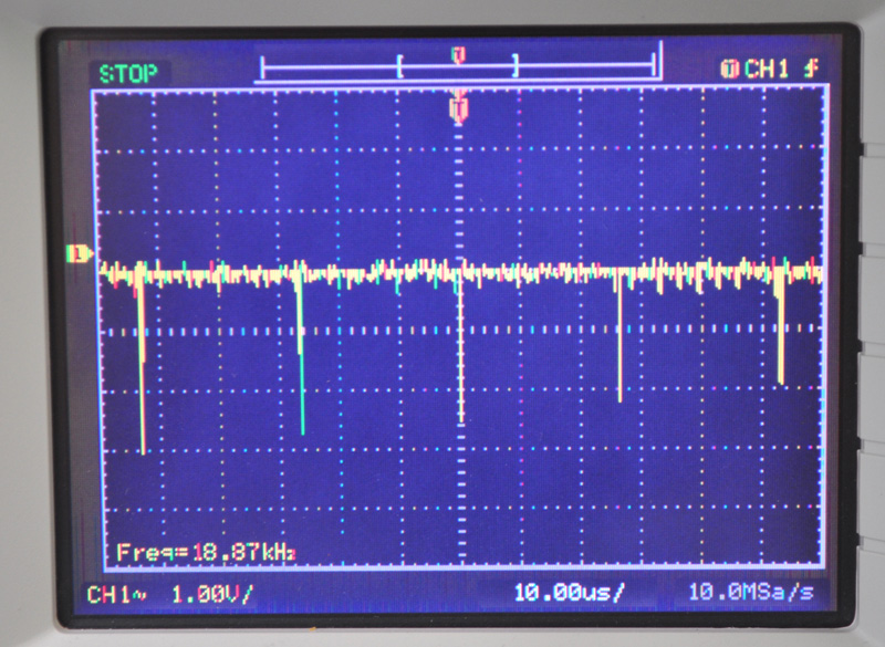
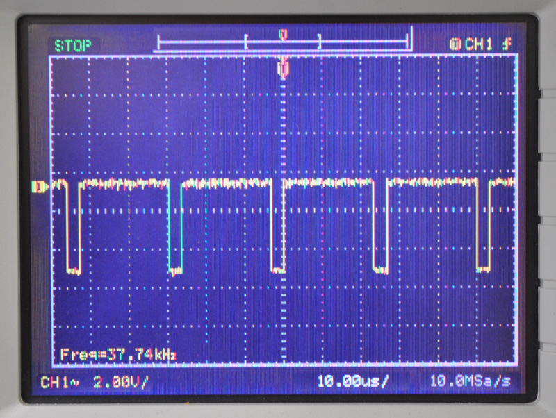
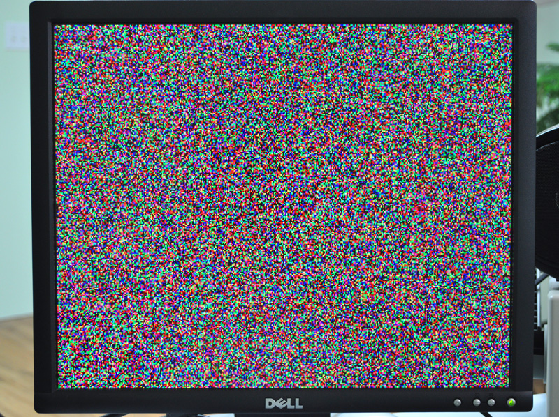
A few ns of lag and the dreaded fat/skinny first/last pixel issues rears its ugly head.
Not so bad on a glass CRT, but horrible banding on an LCD.
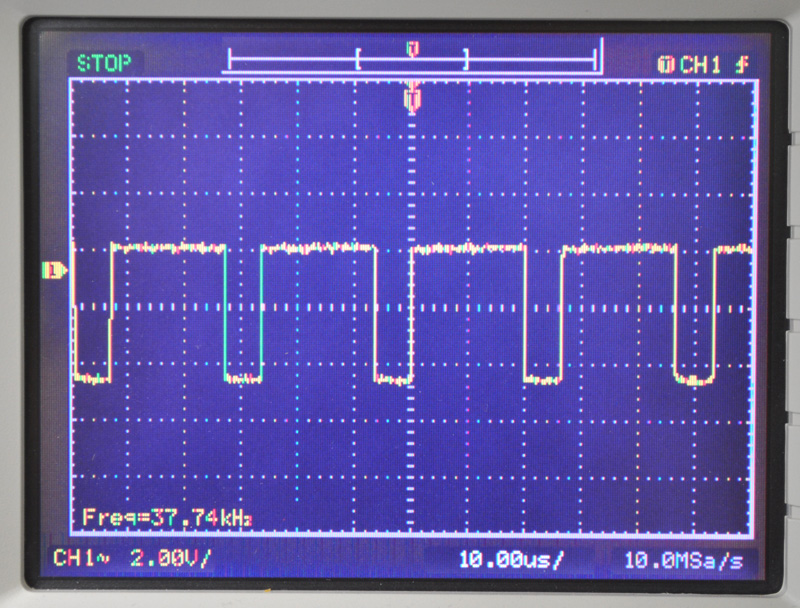
All outgoing signals MUST sync to a clocked register.
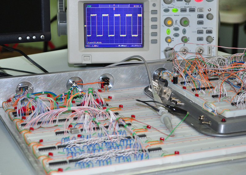
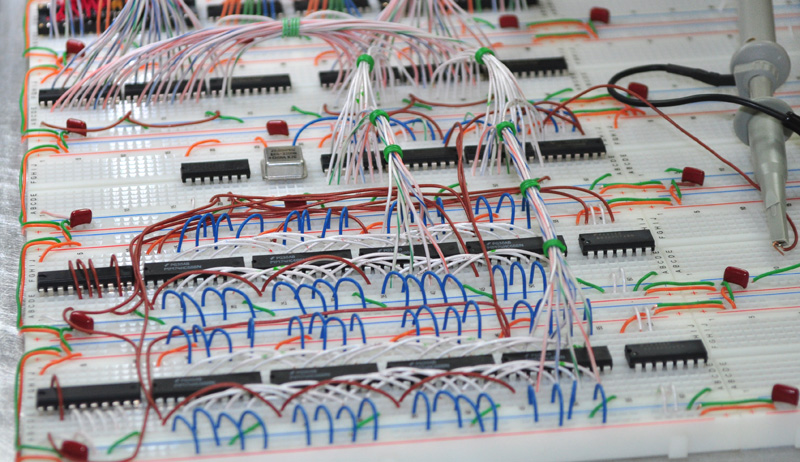
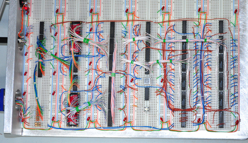
Funny, I could probably generate VGA with a handful of 555 timers, one-shots, and some 1970's op amps, but try to make 100% perfect VGA and draw a single pixel border around the edge of the screen (0,0-399,299 in my case) without banding, fuzzng, or thickness variations... now that's another thing altogether! Challenging even on an FPGA so I have found out.
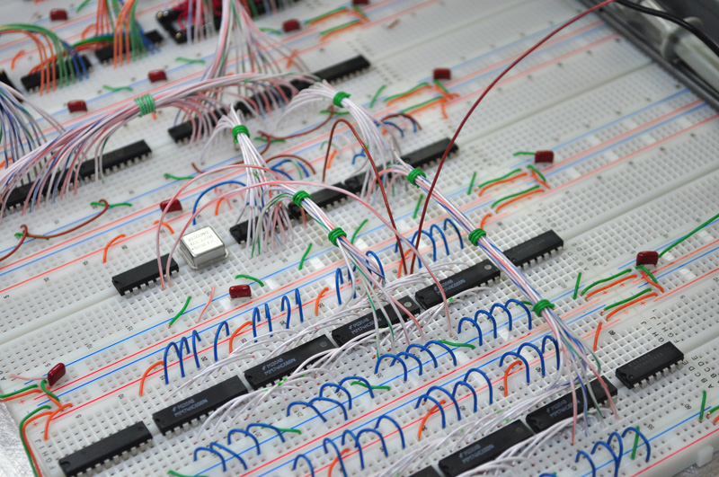
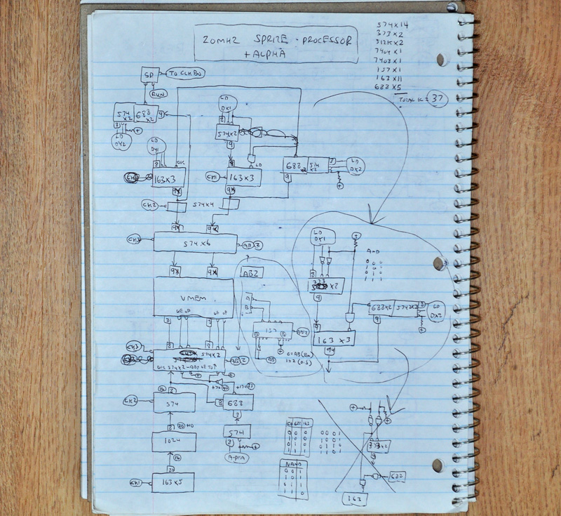
I use the 163's quite a bit in other parts of this project, but in the video addressing circuit, I had to stick to the 590's for reasons I will get into as I detail everything.
I use them in another circuit I call "fast clear" as well, which is clocked at an amazing 50Mhz on this breadboard!
163's didn't like that kind of speed.
Thanks,
Brad
Dr Jefyll wrote:
Quote:
you wouldn't have to use pull-down resistors to hold the low level required during blanking, but alas, there would be another problem.
To provide the absolute timing regularity that video demands, it's pretty well obligatory to arrange things so a single clock signal updates both pixel data and blanking.
I would consider replacing the '574 with a pair of '163 counters, which offer synchronous load and synchronous clear, both from a single clock. ('163s are great little chips -- good for so much more than just counting!)
cheers,
Jeff