A message from the original poster.
This thread is about my build of a Micro UK101, a Compukit UK101 replica comprised of readily available, standard components. It was designed by Grant Searle and can be seen on his UK101 hardware page here : http://searle.hostei.com/grant/uk101/uk101.html. The result is a useable hobby computer that can be programmed in BASIC or 6502 machine code.
There is a good deal of useful information and advice on the thread and because I'm fairly new to this sort of thing, the questions I asked were suitable for someone starting out.
Should you decide to build one, you may be interested in a small tweak to the clock circuit which is discussed later on in the thread (see here -> viewtopic.php?p=14221#14221). I had to do this because the original clock circuit didn't work when I built it (even after doing it a second time round on a separate board). However, since it's so easy to change, I'd advise building the circuit as-is and only modifying it if you have problems.
This is a great little project to get you started in the world of retro hardware hacking, and as you'll see from the thread, we have here a helpful community of active experts, so you should be able to get all the help you need if you have difficulties (like I did).
Good luck with your build!
JonB / micro_brain
Hi all
I stumbled across Grant Searle's UK101 pages and decided to have a go at building one (this because I really wanted a UK101 when I was 15 but knew my Dad would never stump up the cash). I ended up with a ZX81 in kit form which I had up and running in about four hours. Anyway, I have acquired all the parts needed apart from the 6502 (ordered, but hasn't turned up) and the prototyping wire.
Now, before I dive into this wiring marathon... has anyone apart from GS built one, and if so, are there any problems I should be aware of? Hardware? Software? GS has altered the CEGMON monitor for RS232, are there any bugs I should know about?
Question 2: On the website, GS says it can support a second serial interface for program loading / saving. I can't see how - unless the ASIC has a second channel (which means - I guess - I'd need another MAX232 IC. But is this necessary, or does the existing interface support it? And if so, what happens to the terminal you're using to issue the LOAD/SAVE command in?. Do you just capture the text?
Sorry for the basic questions. I'm a novice at this (although I know a bit about hardware interfacing - enough to build it but not to fully understand).
Thanks
micro_brain
Micro UK101 Build
-
micro_brain
- Posts: 85
- Joined: 31 Mar 2011
Micro UK101 Build
Last edited by micro_brain on Tue Dec 04, 2012 9:01 pm, edited 4 times in total.

I haven't built one, but it does look like a nice project. I had (and still have) a UK101 - I fired it up a year or so ago(*), but it was a bit wobbly and then the power supply failed. Surely fixable, but not yet worth doing.
You had me confused for a bit with 'ASIC' but I see now that you mean 'ACIA' - I think the answer is that this isn't a dual-channel part so you'd need to swap for one which is, or leave room for a second one and figure out the decoding for it. (And in both cases you'd need to patch the code and re-program the ROM - I suppose you have to have a way to do that though for the unmodified ROM.)
Good luck, and I look forward to seeing pictures!
Ed
(*) I can't believe this: it was 7 years ago... how did that happen?
-
leeeeee
- In Memoriam
- Posts: 347
- Joined: 30 Aug 2002
- Location: UK
- Contact:
Yes I built one and it worked fine but I fairly quickly wrote my own monitor and not quite so quickly reverse engineered the BASIC and developed EhBASIC.
If you use a PC host as the terminal then loading and saving can be done with text send and capture from within the terminal program.
To load something just type NEW[enter] to erase any old program and then send the source text, no need to type LOAD as you're faking typing the program in. Saving is done by typing LIST, turning on text capture and then hitting [enter] and waiting for the program to list before ending the text capture.
Cheers,
Lee.
-
leeeeee
- In Memoriam
- Posts: 347
- Joined: 30 Aug 2002
- Location: UK
- Contact:
Oh wait, I do remember one samll problem.
On the original UK101 programmes were saved with ten trailing null bytes at the end of each listed program line. This was to allow the interpreter time to crunch each program line and copy it to memory before the next line began.
Whichever terminal program I was using ignored the null bytes when text capturing so I had to edit the source files by padding the beginning of each program line with thirty or so space characters, for the faster serial rate, which seemed to give enough time.
When I made another 6502 SBC I implemented hardware handshaking so padding the lines was no longer needed.
Cheers,
Lee.
-
micro_brain
- Posts: 85
- Joined: 31 Mar 2011
Right then, game on
So it does work... great.
Yes, I meant ACIA (dunno why I keep thinking ASIC)... I thought that the LIST output capture was the technique (I was hoping not..) - a bit clunky but good enough for now.
Just waiting for the 6502 & prototyping wire then I can begin. I also ordered a cheap eeprom programmer and an eraser, so I might be looking to "upgrade" the firmware once I get it going.
Incidentally, GS says it can run at 8Mhz, is this possible? I read that you'd need fast eeprom to do this. If so, how to alter the speed?
Cheers
JonB
-
leeeeee
- In Memoriam
- Posts: 347
- Joined: 30 Aug 2002
- Location: UK
- Contact:
To run at a different speed you use a different divide output from the 74LS93. To run at 2MHz use Qc (pin 8), at 4MHz use Qb (pin 9) and 8MHz use the output from the 8MHz oscillator.
Apart from needing fast enough memory though you will also need both a faster rated 6502 and 6850. Mine ran happily at 2MHz with 2MHz 6502 and 6850 and 120ns memory.
Cheers,
Lee.
Apart from needing fast enough memory though you will also need both a faster rated 6502 and 6850. Mine ran happily at 2MHz with 2MHz 6502 and 6850 and 120ns memory.
Cheers,
Lee.
-
micro_brain
- Posts: 85
- Joined: 31 Mar 2011
Hi Lee,
I guess I'd better get it built at 1Mhz first. If it is stable I will attempt to overclock, but I need to see how fast all the parts are first. Of course, knowing my luck I'll mess the wiring up and it'll do nothing. Or my cheap Chinese EEPROM programmer won't work (has not arrived yet..). No fancy logic probes here, I am strictly a beginner and I don't even have an oscilloscope. I am going to use .25mm wire, the sort that looks like transformer wire but is solderable without stripping first. But darn it, it sure is hard to buy in the UK!
Anyone else that is interested, you an get it here : www.wires.co.uk and they call it "solderable enamelled copper wire". I'm going to make a wiring pen too.
You wrote a 6502 BASIC, did you not? Is it compatible with the Micro UK101?
Incidentally, I read the UK101 manual and it says the tape load / save is just as primitive as the "capture via terminal" technique. I would love to add a disk drive to it, but obviously I have no idea about how to do it. I need to look into how it was implemented on the original UK101. Ideally I'd like some sort of flash based solution, maybe with a CF card. Plenty of space on my tripad veroboard for that
By the way, thank you very much for your advice. I know how difficult it is talking to noobs!
Cheers
JonB
-
leeeeee
- In Memoriam
- Posts: 347
- Joined: 30 Aug 2002
- Location: UK
- Contact:
Quote:
Of course, knowing my luck I'll mess the wiring up and it'll do nothing. Or my cheap Chinese EEPROM programmer won't work (has not arrived yet..). No fancy logic probes here, I am strictly a beginner and I don't even have an oscilloscope.
http://www.themotionstore.com/leeedavis ... index.html
.. while you get the clearest results with a 'scope you can do some tests with just a peizo sounder.
Quote:
I am going to use .25mm wire, the sort that looks like transformer wire but is solderable without stripping first. But darn it, it sure is hard to buy in the UK!
The wire I have is a 1Kg reel of no name .32mm enamel. I must have had it for more than 25 years but I still have a bit to go.
I use this method for nearly all wiring except power connections which I do with solid copper, as can be seen on this page ..
http://www.themotionstore.com/leeedavis ... index.html
Quote:
You wrote a 6502 BASIC, did you not? Is it compatible with the Micro UK101?
Quote:
Incidentally, I read the UK101 manual and it says the tape load / save is just as primitive as the "capture via terminal" technique.
Quote:
I would love to add a disk drive to it, but obviously I have no idea about how to do it.
Quote:
I need to look into how it was implemented on the original UK101.
Quote:
By the way, thank you very much for your advice. I know how difficult it is talking to noobs!
Cheers,
Lee.
-
micro_brain
- Posts: 85
- Joined: 31 Mar 2011
Do you think .25mm is too fine? I don't know what it is like to work. I'm concerned it'll be a bit like hair and won't be stong enough to take the loads or hold its shape once bent into position.
This is so frustrating. There's nowhere you can go to handle these components, to see what they're like, and you have to mail order everything (I'm still waiting for the 6502 after a week). Naturally there will be something I have missed (eg, those header sockets for power, serial and expansion).
Oh, talking of expansion - apart from the address and data lines, what signals ought I to include on an expansion port? I've seen a few designs (GS's schematic doesn't show any but there are labels on the photo that offer some clues). I'm not sure I'll ever bother expanding it, but I'd like the opprtunity. Of course I can always add this later, if I leave enogh free space on the board.
Can't wait to get started....
By the way, I'll be using normal insulated link wire for vcc and gnd lines.
These people (roadrunner) sell wiring pens and plastic combs (which they call glue strips) - somewhat cheaper than verowire's parts, I gather.
Their wire is 0.15 or 0.19mm!
The plastic combs help a lot with keeping the result tidy - you end up with manhattan routing rather than point-to-point. Like this (our 65816 add-on for a Beeb):
Their wire is 0.15 or 0.19mm!
The plastic combs help a lot with keeping the result tidy - you end up with manhattan routing rather than point-to-point. Like this (our 65816 add-on for a Beeb):
Last edited by BigEd on Wed Mar 27, 2019 9:22 pm, edited 1 time in total.
-
GARTHWILSON

- Forum Moderator
- Posts: 8775
- Joined: 30 Aug 2002
- Location: Southern California
- Contact:
micro_brain, here is the back of an LED display board I made for my first home-made computer (shown here), using enameled wire that was about .35mm diameter:
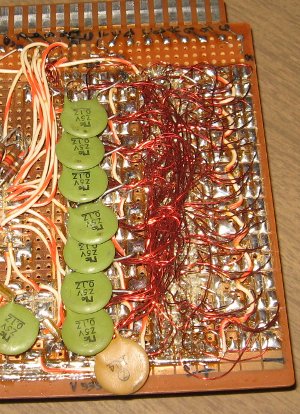
This was in 1985. It was much harder to work with than wire wrap, but I wanted the board to be thin. Yes, I did break some wires, because they had to be bent back and forth to give access to adjacent places I was soldering, and there was also the problem of defeating the enamel insulation accidentally with the soldering iron while trying to solder a different wire next to it. I would never do it again. Wire-wrap, when done correctly, is faster, totally reliable, and probably allows better density.
Below is my wire-wrapped workbench computer (with outdated pictures and diagrams shown here before subsequent expansion), with wall-to-wall parts, obviously done with wire-wrap:

Your ideas will never stop evolving, even to build what you think would be best at the time you start the build. I have done a few iterations though and evolved and expanded my primary workbench computer for nearly 20 years now. For many of those years I was planning my next workbench computer to have more I/O (especially different expansion buses), more speed, more memory, etc., but as I gained experience with what I had on the workbench, I found ways to expand it which breathed new life into it, and I began to see that the expansion buses and various things I thought I needed were not only unnecessary, but were getting so complex that I wouldn't live long enough to carry out my ideas.
This is one area where the thousands of synchronous-serial (not asynchronous like RS-232) ICs on the market shine. Our 65SIB serial bus spec. accommodates a wide range of serial devices. We will also be supplying tiny modules for I²C, so for example, you can plug in a half-postage-stamp-sized serial EEPROM or real-time clock, with a standardized 6-pin connector. For the things that don't need absolute maximum speed, the synchronous-serial parts dramatically reduce the wiring work and the board space required to implement something. You can even get floating-point math coprocessors in synchronous serial (although the writers of the linked website overlook the fact that there are really slick ways to do the same things with fixed-point and scaled-integer math that puts a lot less burden on a computer than floating-point does).
This was in 1985. It was much harder to work with than wire wrap, but I wanted the board to be thin. Yes, I did break some wires, because they had to be bent back and forth to give access to adjacent places I was soldering, and there was also the problem of defeating the enamel insulation accidentally with the soldering iron while trying to solder a different wire next to it. I would never do it again. Wire-wrap, when done correctly, is faster, totally reliable, and probably allows better density.
Below is my wire-wrapped workbench computer (with outdated pictures and diagrams shown here before subsequent expansion), with wall-to-wall parts, obviously done with wire-wrap:
Your ideas will never stop evolving, even to build what you think would be best at the time you start the build. I have done a few iterations though and evolved and expanded my primary workbench computer for nearly 20 years now. For many of those years I was planning my next workbench computer to have more I/O (especially different expansion buses), more speed, more memory, etc., but as I gained experience with what I had on the workbench, I found ways to expand it which breathed new life into it, and I began to see that the expansion buses and various things I thought I needed were not only unnecessary, but were getting so complex that I wouldn't live long enough to carry out my ideas.
This is one area where the thousands of synchronous-serial (not asynchronous like RS-232) ICs on the market shine. Our 65SIB serial bus spec. accommodates a wide range of serial devices. We will also be supplying tiny modules for I²C, so for example, you can plug in a half-postage-stamp-sized serial EEPROM or real-time clock, with a standardized 6-pin connector. For the things that don't need absolute maximum speed, the synchronous-serial parts dramatically reduce the wiring work and the board space required to implement something. You can even get floating-point math coprocessors in synchronous serial (although the writers of the linked website overlook the fact that there are really slick ways to do the same things with fixed-point and scaled-integer math that puts a lot less burden on a computer than floating-point does).
http://WilsonMinesCo.com/ lots of 6502 resources
The "second front page" is http://wilsonminesco.com/links.html .
What's an additional VIA among friends, anyhow?
The "second front page" is http://wilsonminesco.com/links.html .
What's an additional VIA among friends, anyhow?
-
micro_brain
- Posts: 85
- Joined: 31 Mar 2011
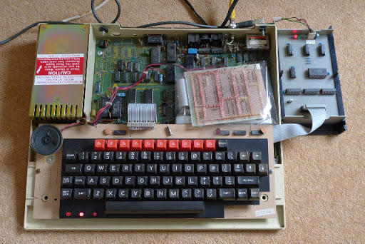
Thanks for the great advice and lovely pictures! Liking the Beeb, Ed. Gareth, I thought about the possibility of accidentally going through some insulation whilst soldering another wire, and I am going to have to pay close attention to the routing to try and reduce the possibility. GS's back picture doesn't look as dense as your LED board, so I may be in luck.
Fortunately, the Vero pen turned up this morning so I could start as I have all the other components apart from the 6502 and EEPROM programmer / eraser (from China - TOP853).
I have to say, I'm not sure what wire is in the pen, but it looks awfully thin to me... still... "Who Dares Wins"
[EDIT : OMG It's .2mm!!! Argghhh!]
All I need now is a little spare time <sigh>
Up next : more noobie questions....
-
micro_brain
- Posts: 85
- Joined: 31 Mar 2011
...Done...
Phew. Done the wiring. What a fiddly job. There appear to be a lot of dry joints which I think are caused by the wire insulation as it burns off. The next step will be to test it with a continuity checker, then fix any errors (found a couple already). Obviously see what I can do about the dry joints.
I think it would be much better to do this on a proper PCB. It would be up and running in an hour with one of those.
Anyway, will post some pictures when I get time. Mother's day and apart from breakfast I've been all but missing in action. My name is mud!

I think it would be much better to do this on a proper PCB. It would be up and running in an hour with one of those.
Anyway, will post some pictures when I get time. Mother's day and apart from breakfast I've been all but missing in action. My name is mud!
This is an interesting project, I was looking at the clock circuit and was wondering if someone could explain why he takes 8Mhz to 1Mhz instead of just a 1Mhz xtal ? What purpose does it serve? I haven't looked at the ASIC datasheet to figure out why its being fed a 307Khz signal, I am guessing for the baud rate.
So the next thought that came to mind is it possible to use such clock divisions to run a CPU at 8Mhz and run slower legacy devices at a 1Mhz clock rate? every 8th clock the legacy device would spew its data? Reason Im asking is I found a couple of 6551's in the parts drawer and would sure like to use but not if the CPU has to be slowed down to 1Mhz.
Should work right? Seems like common practice to run the CPU at one speed and the hardware/pci/isa stuff at another speed.