Update 2023-09-16: Keyboard hacked, NVRAM backup, Planning soldered breadboard, Potential fanout issues, Improved clock module
Keyboard hacked:
To avoid using USB and any associated CPUs, and to get lower keypress latencies and better overall control of the keyboard access, I’ve bypassed the KB120 onboard controller and connected wires directly to the keyboard contact matrix. This matrix is formed out of two clear plastic sheets that are each made into a kind of circuit board with silvery traces, but can’t be soldered at any temperature significantly above room temperature. I used the original controller board just to get the connector fingers. Unfortunately these are covered in black, evidently carbon-rich gunk that is hard to get off. After a lot of scraping and using Q-Tips with 91% isopropyl alcohol, I was able to solder hookup wire to the original pads and put them into the crimping system that the keyboard came with. Here is the result, with the keyboard all put back together:
Attachment:
File comment: Keyboard KB120 hacked to get direct connections to the contact matrix
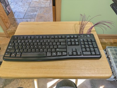 LRC-keyboard-hacked-matrix-lines.jpg [ 3.83 MiB | Viewed 2561 times ]
So far, my spot checks on the matrix connections with a ohm meter indicates this was successful, and I should be able to make a controller/scanner circuit to detect and record keypresses to send to the CPU later.
NVRAM backup:
Earlier in this thread was the suggestion to make backups of the NVRAM that I am working hard to put code into and do laborious font editing. Since the system with NVRAM can be easily corrupted by the CPU running amok (for hardware or software reasons), backups seemed like a priority now.
The module I came up with is ridiculously simple, just two 74F chips, plus a bunch of clock lines from the clock module, a pushbutton switch and a pull-up resistor, plus two sets of five bank-select switches with associated pull-up resistors. The chips are a 74F174 quad flip-flop, and an OR gate. These are used to form the WE\ pulse and CS\ signal on the NVRAM being written. The NVRAM being read from just has all its control lines hooked to +5 or ground as appropriate. Here is the resulting module:
Attachment:
File comment: NVRAM backup copier module
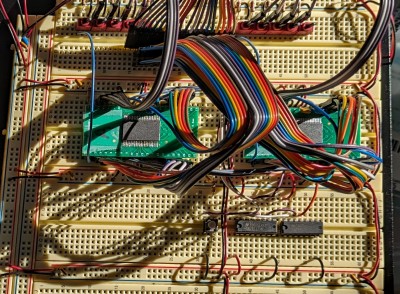 LRC-NVRAM-backup-copier-module.jpg [ 1.92 MiB | Viewed 2561 times ]
I’ve used this and spot checked the resulting copy. Each NVRAM has 32 banks of 64k each. I also managed to correctly solder three out of five of the NVRAM surface mount chips to the adapter boards. Two of the five were damaged, with certain bits pinned high. I’m glad I splurged to buy a hot air rework station and stencil/squeegee things to apply solder paste to the wee little surface mount pads.
Planning soldered breadboard
Since the proliferation of solderless breadboards was getting out of hand and started to be very finicky to keep going, I’ve decided to make a soldered version of the CPU+video modules, plus some generic memory-mapped I/O parts of the font editor module. My self-designed generic breadboards support only three rows of chips if you don’t cut traces, but I realized that by cutting some traces like you would with stripboards, I could pack six rows of chips onto the breadboard. The tricky thing is to optimize/arrange the layout of the chips and trace cuts to support all the wire connections needed. Here is a diagram I started working on to do this:
Attachment:
File comment: Soldered locker-room-challenge initial board layout puzzle
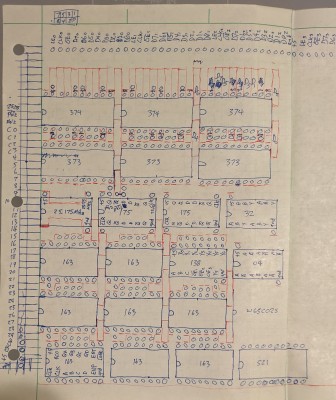 LRC-soldered-layout1-20230915.jpg [ 2.24 MiB | Viewed 2561 times ]
The red lines are where the trace cuts (or edge of the board) would go. Note that I’ve put space between chips that can act as wire fanout enhancers for high-fanout lines like some important clock lines. Anyway, this is an interesting puzzle to work out. Here is what the layout looks like when I put sockets, unsoldered for now, into the breadboard to see how things would work out of what issues might arise:
Attachment:
File comment: LRC actual breadboard testing initial layout
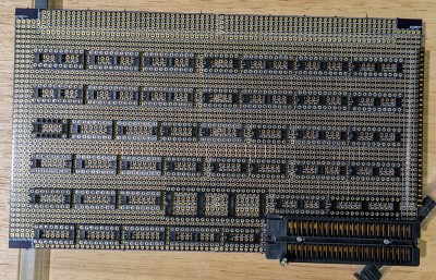 LRC-soldered-layout1-checking-it-out.jpg [ 1.39 MiB | Viewed 2561 times ]
The ZIF socket for the NVRAM is a real beast, pushing things away and causing layout grief. It is also very high profile, as is the NVRAM on its adapter board, so any module stacked on top of these will need a cutout in that corner.
Potential fanout issues
I hadn’t really been thinking about fanouts being an issue, as generally a decent logic family like 74F has something like 30+ fanout if you stick with the same family. However, as I was planning my soldered LCU (Locked Room Challenge) SBC, and adding lots of bytes of latched+buffered memory-mapped I/O, I started to worry about fanout with respect to the W65C02S CPU. Looking at the data sheet I was horrified to see that the CPU can only be expected to drive 1.6 mA (the Iol max rating), which is able to output to less than three 74F inputs! Yikes! I’ve seem some mention on the forums that this part of the WDC data sheet is extremely conservative, but I don’t want to design into dicey territory. So I’m planning to latch the address and data lines on CPU write, and from there write to a bunch of output latches. I will actually reuse the three 74F374 latches I am currently using for the CPU-to-video-ram write, and have that be used for both memory-mapped output generally as well as video ram writing.
In any case, this has caused me to rethink my design to make other improvements I’ve been thinking about. Back to my first module, the power-of-two clocks bank, I’ve found it messy and potentially limiting to have my higher frequency clocks asynchronous from each other (25 12.6 and 6.3 MHz don’t line up with each other). Solution below.
Improved clock module
So to get 25.175 MHz and all divisions by two from that to line up, it helps to have a 50.35 MHz clock to drive these. I have not seen this specific frequency of oscillator module for sale, so I decided to make my own by making a frequency-doubling circuit for my 25.175 MHz clock signal. There are a large number of ways to do this, including some fast analog filtering and rectification bridges, but the simplest seems to be to add a delay line chip to get a ¼ cycle delay and XOR gate inputting the original and delayed clock signal. Initially I just used three 74F04 inverters in series for an appropriate delay, and it worked, but this is really fragile in several ways, and not reliably repeated on a second build or tolerant of parts swaps or temperature changes etc. So I’ve put to use the Maxim DS1100Z-20+ silicon delay line module, that has five taps at multiples of 4ns delay. I use tap 3, nominally 12ns, since that seemed to give a slightly better 50MHz signal with the limited visualizations I could do on my cheap scope. I suppose I could have put in an automated duty cycle optimization circuit based on averaging the clock signal over a long (1000’s of cycles) time window, and comparing to an ideal voltage, but I just want to move on for now.
In addition, I wanted to improve so that all my highest frequency signals have symmetric inverted variants. So I designed my own “enhanced” `163 counter-like circuit using 74F175 quad flip flops and various supporting gates. The flip-flops output symmetric inverted/non-inverted pairs.
Also, since I am clocking all my counters at a *much* higher 50MHz, I went with the fast `163 circuit design, separating the high-frequency part of the carry look-ahead to the ENP pins on the counters all connected together, and the propagation-delay low-frequency chain on RCO-ENT-RCO-ENT-... Here is the overall schematic (LRC appropriate – no computers used!):
Attachment:
File comment: LRC improved clock module schematic
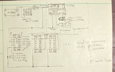 LRC-clock-module-improved-schematic-20230916.jpg [ 540.85 KiB | Viewed 2561 times ]
Overall this works great, and I have 32 synchronous power-of-two clock signals going from 25.175 MHz down to a cycle time of around 85 seconds. I believe this will help make for a simpler design and timing analysis process, and hopefully more reliable designs at the end. Here is the prototyped module in action:
Attachment:
File comment: LRC improved clock module in action
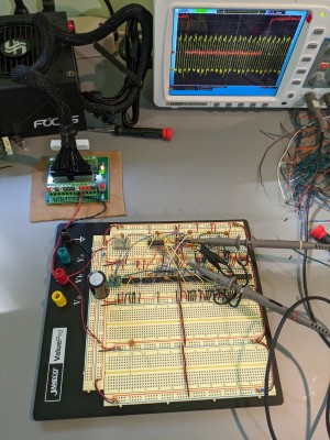 LRC-improved-clock-module-in-action.jpg [ 7.51 MiB | Viewed 2561 times ]
My next steps are to work out the revised LRC SBC design with the fanout from the CPU minimized, redo the layout once that is done, and start soldering.


