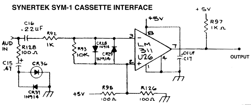
This is only tangentially 6502 related, I hope you all won't mind my posting it here. I've been looking at the cassette input circuit on the Synertek SYM-1 schematics. Here's the relevant section:
I understand the principle behind the circuit, but I don't understand why the value 100 ohms was chosen for the two resistors in the voltage divider (marked R95 and R126 in the schematic). My understanding is that the 2.5V from this divider serves as a reference voltage on the non-inverting input of the comparator, as well as providing a +2.5V bias to the cassette audio signal on the inverting input, correct? But it seems to me that any resistor values could have been chosen. The 200 ohm resistance between +5V and ground means the circuit is always consuming at least 25 mA, it seems like a higher value would make more sense. So, I assume there's something I'm missing from my understanding
I still consider myself a real neophyte when it comes to hardware (I've been a software guy much longer), so I really appreciate it when I can get guidance from experienced folks. It's the best way to learn.
My understanding is that the 2.5V from this divider serves as a reference voltage on the non-inverting input of the comparator, as well as providing a +2.5V bias to the cassette audio signal on the inverting input, correct?
Yes that's right. But that node -- the junction of the 100 ohm resistors -- also connects to the two 1N914 diodes. It looks as if these are intended to clip the input signal arriving via R92. To clip effectively and yet still stay centered around the 2.5V point requires that the node have low impedance as compared with R92 (1K).
You're right in saying it's a waste of power, but it's cheap and it works. A slightly more expensive alternative would be to bypass the node to ground by adding a suitable capacitor (effectively about zero ohms at audio frequencies). Then higher-value resistors could be used in place of the 100 ohm units, reducing power. To be fussy about it, you could put 50 ohms in series with the new cap; then you'd have a closer match to the existing circuit -- roughly 50 ohms at the node in question. At least that's my take on the situation
cheers
Jeff
Last edited by Dr Jefyll on Sun Jan 06, 2013 3:09 am, edited 1 time in total.
My understanding is that the 2.5V from this divider serves as a reference voltage on the non-inverting input of the comparator, as well as providing a +2.5V bias to the cassette audio signal on the inverting input, correct?
Yes that's right. But that node also connects to the two 1N914 diodes. It looks as if these are intended to clip the input signal arriving via R92. To clip effectively and yet still stay centered around the 2.5V point requires that the node have low impedance as compared with R92 (1K).
That's what I thought also, that since it's "aud in" (meaning audio in, I assume)
it's probably not line level and clipping is expected as part of normal operation.
Quote:
You're right in saying it's a waste of power, but it's cheap and it works. A slightly more expensive alternative would be to bypass the node to ground by adding a suitable capacitor. That would provide low AC impedance -- and higher-value resistors could be used in place of the 100 ohm units. At least that's my take on the situation
cheers
Jeff
Don't know what sym-1 uses but you'd want some encoding with no DC component for that
(like Manchester encoding)
These days some jelly bean op amp active virtual ground makes more sense I think.
But I'm kind of suprised there isn't a capacitor or two on the resitor divider.
Especially since C16 is only .22uF and R92 is 1K, it definitely makes more sense to make R95 and R126 much higher and bypass them with a 10uF capacitor. CR28 and 29 don't do anything to protect the inputs of the comparator. Some comarators and op amps need that but the LM311 can handle a differential voltage of up to +/-30V. Since it's a comparator, the output will clip anyway, so the diodes aren't needed for clipping. The circuit designers at the computer company were apparently pretty weak in analog design.
-- the junction of the 100 ohm resistors -- also connects to the two 1N914 diodes. It looks as if these are intended to clip the input signal arriving via R92. To clip effectively and yet still stay centered around the 2.5V point requires that the node have low impedance as compared with R92 (1K).
That's also how I see it.
GARTHWILSON wrote:
Some comarators and op amps need that but the LM311 can handle a differential voltage of up to +/-30V. Since it's a comparator, the output will clip anyway, so the diodes aren't needed for clipping. The circuit designers at the computer company were apparently pretty weak in analog design.
It's true that the comparator will clip its output, but you did miss this little caveat on page 4 of the LM311's data sheet:
3. The magnitude of the input voltage must never exceed the magnitude of the supply voltage or ±15 V, whichever is less.
That explains the clamping circuit. It's there to prevent the inputs from being overdriven.
3. The magnitude of the input voltage must never exceed the magnitude of the supply voltage or ±15 V, whichever is less.
Then the diodes should go to power and ground, because it doesn't do any good to have them both go above or below together.
R93 will keep the inverting input's signal centered on 2.5V.
If the diodes went to the power supply rails, the input voltage would exceed the power supply voltage by a diode drop before the diodes started clipping. This would take the LM311 outside its design limits and possibly cause it to be damaged. By clipping to a mid-rail voltage, the LM311 input doesn't get overdriven.
I'm surprised at how low all the resistor values are in this circuit. It would work just as well if all the resistors were made 10 times as large and a capacitor used to decouple pin 2 of the LM311 (say 10uF or 22uF)
Shift to the left,
Shift to the right,
Mask in, Mask Out,
BYTE! BYTE! BYTE!
If the diodes went to the power supply rails, the input voltage would exceed the power supply voltage by a diode drop before the diodes started clipping. This would take the LM311 outside its design limits and possibly cause it to be damaged. By clipping to a mid-rail voltage, the LM311 input doesn't get overdriven.
The diodes should be Schottky ones, so even if parasitic or protection diodes in the IC get some forward voltage, it won't be enough to hurt anything. If there's any doubt, series resistors can be added to pins 2 & 3 with optionally a 22pF capacitor across each of those two resistor to eliminate the pole formed by the resistor and the input capacitance of the IC.