6502.org Forum  Projects  Code  Documents  Tools  Forum
It is currently Sat Apr 27, 2024 3:03 am

All times are UTC


Post new topic Reply to topic  [ 41 posts ]  Go to page 1, 2, 3  Next
Author Message
PostPosted: Tue Dec 15, 2009 6:00 pm 
Offline
User avatar

Joined: Fri Aug 30, 2002 1:09 am
Posts: 8428
Location: Southern California
This is to bring to everyone's attention two things that came up where some members might not be interested to check (although they should be :) ) . One is from a 65816 topic and one from the Forth section.

In the topic "I/O not in bank 0" under "Hardware," BigDumbDinosaur wrote:
Quote:
I've yet to see a satisfactory method of mounting BGA silicon by hand. I have a hard enough time with SOJ, etc.

I've found SOJ and SOIC to be surprisingly easy to solder. A paragraph from my post a few years ago:
Quote:
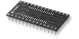
For some of the surface-mount parts, you can get adapters to thru-hole. Aries is one manufacturer of such parts and their prices are far better than Ironwood's. Mouser and Digi-Key carry Aries parts. With these adapters, you can use standard IC sockets in breadboards with holes on a .1" grid. Soldering the SMT part to the adapter is much easier and quicker than you might think. Start by soldering a pin or two or three at each of two opposite corners to keep the IC positioned as you soler the rest. This is the most critical part, where it's important to make sure the pins are centered on the right pads. After that, you can just run down a row of pins with the solder and iron, with no concern for bridges. After all the pins are soldered (and it looks a mess), hold the board or adapter up vertically and run the soldering iron down (not up) a row of pins and the excess solder will come off onto the iron and leave the pins soldered perfectly with the same amount of solder on every pin, and no bridges. You don't need a tiny iron that can solder one pin at time, and you don't need ultra-small-diameter solder. Extra flux from a tube helps, but you can do it without it too. It's ok if the soldering iron tip covers three pins at a time. Just be careful not to bend SOIC pins.


Aries and other manufacturers offer adapters to make SOICs and other SMT parts able to be plugged into DIP sockets. Here's a page of Aries ones, some of which I've used: http://www.arieselec.com/products/overv ... apters.htm ; and an example:

Image


And in the topic "6502 Forth with hardware accelerator" in the Forth section, BigEd wrote:
Quote:
...is also a win: the FPGA can be on a 5v-friendly 40-pin DIP module, at the cost of an external latch. Then the board design stays in familiar 0.1" pitch, through-hole, 5v territory. [...] I'm not ready to solder surface-mount devices, but I want the flexibility of CPLDs and FPGAs, and I've got a 5v system to build on. I've got a couple of these DIL modules, and they should be suitable to experiment with variations on the 6502 theme.

The other alternative is PLCCs, which can be put in sockets-- even wire-wrap sockets-- that fit into breadboards with the holes on a .1" grid. I got my McKenzie Berg PLCC wire-wrap sockets from Allied. Unfortunately Allied doesn't seem to have them anymore, nor does http://smt-adapter.biz/ . However, BigEd pointed us to a source that stocks WW PLCC sockets in many sizes: http://uk.rs-online.com/web/c/?searchTe ... ra=oss&r=t .

Here's a picture of one of my 44-pin ones:
Attachment:
WW_PLCC_44a.jpg
WW_PLCC_44a.jpg [ 54.55 KiB | Viewed 2924 times ]

Attachment:
WW_PLCC_44b.jpg
WW_PLCC_44b.jpg [ 52.86 KiB | Viewed 2924 times ]

As you can see, it's not one of those more-common monstrosities with a big PC board around the outside and all the WW pins outside the perimeter of the actual socket. It takes no more room than a non-wire-wrap PLCC socket.

_________________
http://WilsonMinesCo.com/ lots of 6502 resources
The "second front page" is http://wilsonminesco.com/links.html .
What's an additional VIA among friends, anyhow?


Last edited by GARTHWILSON on Wed Feb 22, 2012 8:34 am, edited 1 time in total.

Top
 Profile  
Reply with quote  
 Post subject:
PostPosted: Tue Dec 15, 2009 8:52 pm 
Offline

Joined: Mon Sep 28, 2009 3:48 am
Posts: 17
I just picked up one of these boards because Fry's had them.
http://www.schmartboard.com/index.asp?page=products_so

Kind of pricey IMHO but if it works out I will be able to mount 2 chips, class D audio amplifiers ti TPA3120, on one board. Picked up some snap headers too but I haven't decided the layout I want to use yet.

Rick


Top
 Profile  
Reply with quote  
 Post subject:
PostPosted: Wed Dec 16, 2009 12:10 am 
Offline

Joined: Thu Jul 26, 2007 4:46 pm
Posts: 105
I'm going to take delivery of my first SMT boards soon (From BatchPCB) shortly. A few 1206 passives, a slightly bigger diode, an SOIC-8T chip, and a couple of PTH pieces (Bulk electrolytic, high-power resistor and inductor).

The interesting part is going to be the SOIC-8T. The T means thermal pad - theres a big slug of metal on the bottom to dissipate the heat it will be producing. I've strategically placed a via right underneath, so it should be solder-able - we will just have to see whether I manage to do so without shorting the pad to the other pins!

Yes, in this case, the pad is needed; if the board is used to it's maximum specifications, 40V 1A then, since it's worst case is 80% efficiency, it could be dissipating 5W of heat. The board will be mounted to a heat sink - probably one shared by the High-brightness LEDs it's driving!

All in all, it should be interesting


Top
 Profile  
Reply with quote  
PostPosted: Sun Dec 20, 2009 8:35 pm 
Offline
User avatar

Joined: Thu May 28, 2009 9:46 pm
Posts: 8144
Location: Midwestern USA
GARTHWILSON wrote:
A paragraph from my post a few years ago:
Quote:
For some of the surface-mount parts, you can get adapters to thru-hole.

The adapters take up substantially more PCB real estate than the actual part, partially defeating the advantage of small-outline components.

The 50 mil spacing on SOJ parts in itself shouldn't pose too much a problem in soldering. Where it seems most would run into trouble would be in actually getting a secure joint, due to the pins curling under the part. The problem would be in getting the solder to flow to where it is needed.

There's a U-Toobe video in which a technique for soldering a PLCC package directly to the PCB is demonstrated. As the PLCC package has J-leads, I would think the same technique should work with any SOJ part.

_________________
x86?  We ain't got no x86.  We don't NEED no stinking x86!


Top
 Profile  
Reply with quote  
 Post subject:
PostPosted: Tue Dec 29, 2009 6:29 pm 
Offline
User avatar

Joined: Fri Aug 30, 2002 1:09 am
Posts: 8428
Location: Southern California
Above, I wrote:
Quote:
The other alternative is PLCCs, which can be put in sockets-- even wire-wrap sockets-- that fit into breadboards with the holes on a .1" grid. I got my McKenzie Berg PLCC wire-wrap sockets from Allied. Unfortunately Allied doesn't seem to have them anymore, but I found this source. The 32-pin is shown there, but if you click on "Selection-guides" underneath the 32-pin one, it will give you a .pdf file, and the 44-pin is indeed there, part number 44PL-W. At $9.20, they're approximately what I paid quite a few years ago. Here's a picture of the 32-pin:

I couldn't figure out how to order the 20-pin ones from the selection guide, so I Emailed them and asked. The unfortunate response was that they're not making them anymore. Milos wrote:
Quote:
We have to buy pins in very large quantities. As we sell only a few wire-wrap sockets and adapters, we did not buy pins anymore. We are selling sockets which are already pinned (32-pin and 68-pin). When we sell them, we will take them of our web site.

I haven't found any other sources. If someone else has, let us know. Otherwise, if you think you might someday want 32- or 68-pin WW PLCC sockets, better get them now! [Edit, 1/21/13: BigEd just pointed us to a source that stocks them in many sizes: http://uk.rs-online.com/web/c/?searchTe ... ra=oss&r=t ]

_________________
http://WilsonMinesCo.com/ lots of 6502 resources
The "second front page" is http://wilsonminesco.com/links.html .
What's an additional VIA among friends, anyhow?


Top
 Profile  
Reply with quote  
 Post subject:
PostPosted: Wed Dec 30, 2009 2:34 am 
Offline

Joined: Mon Mar 02, 2009 7:27 pm
Posts: 3258
Location: NC, USA
Here's a couple more for ya... I used the thru-hole 44-pin PLCC socket for the 65C02, from http://smt-adapter.biz/ and planted it on wire wrap headers that were trimmed for the socket.

Here's another site I came across early on in my prototyping...

http://www.phoenixent.com/

Edit(01/03/09): Also just found this one. I needed a 28 SOJ to 28 PDIP adapter for a 10ns 8Kx8 SRAM.

http://www.ezprototypes.com/DipAdaptersMain.php

_________________
65Org16:https://github.com/ElEctric-EyE/verilog-6502


Top
 Profile  
Reply with quote  
 Post subject:
PostPosted: Wed Jan 06, 2010 5:36 pm 
Offline

Joined: Thu Jul 26, 2007 4:46 pm
Posts: 105
Code:
Broken external image link
http://static.e43.eu/temp/HBLEDRev02.jpeg

My boards arrived from BatchPCB today. The quality is good, and I can't complain of the quantity - I ordered two and then sent me 8! Perhaps they had some issues with other designs on the panel and had to re-run it 4 times (which does seem excessive!), or perhaps they just had some spare space on the panel and used it to fill in (It's only 1 sq inch). Regardless, I now have more driver boards than I know what to do with!

I'll shortly be doing a beep-out on them, but they certainly all look good.

For timeline purposes, I placed the order on Sat 12th Dec, it was panelized on 14th Dec, and went out for fabrication that day. The boards arrived at their office, and they shipped the package on the 28th Dec, it arrived in the UK this morning. It would have likely arrived quicker if I'd ordered quicker shipping.

The turn around of 2 weeks from order to ship isn't bad for the price, particularly considering the factory was closed for much of it! I'll remember to use faster postage in future though

(Incidentally, I didn't notice how scratched the top of my subwoofer was! Oh, and that mark over the connectors? I'm going to guess thats a cat hair, since the mark doesn't exist on the board)


Top
 Profile  
Reply with quote  
 Post subject:
PostPosted: Thu Jan 07, 2010 7:20 am 
Offline

Joined: Sat Jan 04, 2003 10:03 pm
Posts: 1706
I know this is 100% opposite to what most people are looking to do, but it seems to me that a decent way to gain practice in soldering surface-mount components is to use traditional through-hole parts and bend the leads around the package (emulating a J-lead device) or flatten them out to emulate gull-wing devices. IIRC, the term "flat pack" dates back to the 70s where many hybrid modules were available as 100-mil pitch gull-wing unit.

What are people's thoughts on this?

(I didn't want to start a new thread because it seemed related to what's discussed here. If I'm wrong, feel free to move the message.)


Top
 Profile  
Reply with quote  
 Post subject:
PostPosted: Thu Jan 07, 2010 5:50 pm 
Offline

Joined: Thu Jul 26, 2007 4:46 pm
Posts: 105
The pin spacing is likely to be a problem if you're trying to practice working with SMT parts, as it's likely to make the normal drag solder method unworkable. In other words, you'd end up practicing on something that behaves rather differently.


Top
 Profile  
Reply with quote  
 Post subject:
PostPosted: Thu Jan 07, 2010 8:50 pm 
Offline

Joined: Tue Nov 18, 2003 8:41 pm
Posts: 250
kc5tja wrote:
IIRC, the term "flat pack" dates back to the 70s where many hybrid modules were available as 100-mil pitch gull-wing unit.


I can't say I had a lot of experience with either flat packs or hybrid
modules in the '70s but I think all the flat packs I ever delt with then
had 50 mil spacing and the hybrid modules were all through hole with
100 mil spacing (and I don't think any of them used flat packs they
were all beam lead or flip chip or what ever they called them)

Why not just get an old surface mount board and practice on it?

eg an old motherboard or maybe a memory module.

ps: a surface mount type hybrid module would have been a blessing,
the ceramic substrate on the ones we used generally went to pieces
if the alignment of the leads and through holes wasn't absolutely
perfect.


Top
 Profile  
Reply with quote  
 Post subject:
PostPosted: Thu Jan 07, 2010 10:44 pm 
Offline
User avatar

Joined: Fri Aug 30, 2002 1:09 am
Posts: 8428
Location: Southern California
Quote:
I can't say I had a lot of experience with either flat packs or hybrid
modules in the '70s but I think all the flat packs I ever delt with then
had 50 mil spacing and the hybrid modules were all through hole with
100 mil spacing

My introduction to hybrids in the 80's was that they were basically ICs that plugged into an IC socket but they had multiple silicon chips in them, not just one as with a regular IC. The substrate was ceramic, not normal PC board, and connections to the chips were of course made with bondwires. A frequent example was high-precision A/D converters. After assembly, the cover was brazed on. Pin spacing was .100". I don't seem to be able to find a picture.

Quickly the definition of "hybrid" seemed to change to also include small SMT PC boards that plugged into other boards without necessarily looking like an IC. You can make your own that do plug into an IC socket however with edge pins from Interplex . Unfortunately even a 6502 or '22 in PQFP is too wide to go on a module that plugs into a .600"-pin spacing IC socket, which I think is what stopped us from making a 6502-pin-compatible '816 replacement when we were discussing it some time back at viewtopic.php?t=186. For applications where your hybrid doesn't have to plug into pre-existing boards and sockets, I suppose there's nothing to keep you from cutting a .600" socket and spacing the two rows farther apart, say .800" or even more, and putting more of the circuitry on the hybrid, possibly keeping all the fastest signals onboard so most pins can be used for I/O instead of buses.

I would be more attracted to making these hybrids if there were a good way to mount BGA's at home without expensive equipment. Anyone know? That would be the cat's meow. Then you could even put Cypress's new 4Mx8 SRAM onboard.


Top
 Profile  
Reply with quote  
 Post subject:
PostPosted: Fri Jan 08, 2010 6:43 am 
Offline

Joined: Sat Jan 04, 2003 10:03 pm
Posts: 1706
Ladies and gentlemen, I introduce you to . . . the original flatpack.

http://www.vintchip.com/FLATPACK/flatpa ... 4h00-1.JPG


Top
 Profile  
Reply with quote  
 Post subject:
PostPosted: Fri Jan 08, 2010 11:56 pm 
Offline

Joined: Mon Mar 02, 2009 7:27 pm
Posts: 3258
Location: NC, USA
Heh, is that the datecode on the bottom? Sweet...

_________________
65Org16:https://github.com/ElEctric-EyE/verilog-6502


Top
 Profile  
Reply with quote  
 Post subject:
PostPosted: Tue Jan 12, 2010 4:32 pm 
Offline

Joined: Thu Jul 26, 2007 4:46 pm
Posts: 105
I got one of the PCBs assembled last night. I found the SMT passives to be quite easy; 1206 components are very manageable. 0603s are reputedly easier (in spite of being smaller); I'll have to try them next time. I'd say that the evidence corroborates that though: The SMB diode package was harder to solder; it's also noticeably bigger. Looking from the side, it's not flat; in fact, one of the pads could be said to be floating on the solder.

The chip was slightly more difficult, though largely because I did things backwards and soldered the passives first :oops:. If I'd soldered the chip down first, I'd have had more room to work with. As is, I got a few jumpers and had to use some solder braid.

It took longer than DIP parts, but that's only a lack of practice. Once used to SMT, I can easily see it being much faster, because of the lack of need to thread parts through holes and cut their leads.


Top
 Profile  
Reply with quote  
 Post subject:
PostPosted: Sat Jan 16, 2010 2:56 am 
Offline
User avatar

Joined: Fri Aug 30, 2002 1:09 am
Posts: 8428
Location: Southern California
Does anyone know what's going on with Jameco? For many years, they've sent me the normal catalog updates automatically, but last week I got a thing in the mail from them saying to go to www.Jameco.com/CAT10 to order a free online catalog, so I figured they want to make sure they're only sending it to people who want it. So I go to that address, and it says the page cannot be found, then re-directs me to supposedly the front page I guess, which is blank now-- nothing on it.


Top
 Profile  
Reply with quote  
Display posts from previous:  Sort by  
Post new topic Reply to topic  [ 41 posts ]  Go to page 1, 2, 3  Next

All times are UTC


Who is online

Users browsing this forum: No registered users and 19 guests


You cannot post new topics in this forum
You cannot reply to topics in this forum
You cannot edit your posts in this forum
You cannot delete your posts in this forum
You cannot post attachments in this forum

Search for:
Jump to: