Writing in EEPROM and reading by 6502
Re: Writing in EEPROM and reading by 6502
I think your code is probably correct, given the very simple hardware configuration. Just tie off those input lines and try again.
Re: Writing in EEPROM and reading by 6502
Chromatix wrote:
I think your code is probably correct, given the very simple hardware configuration. Just tie off those input lines and try again.
Re: Writing in EEPROM and reading by 6502
Okay - so we should take another look at your physical circuit layout. You now have a second oscillator in use, and we know that clock edges are a sensitive subject.

Re: Writing in EEPROM and reading by 6502
hitlp wrote:
Chromatix wrote:
Just tie off those input lines and try again.
In 1988 my 65C02 got six new registers and 44 new full-speed instructions!
https://laughtonelectronics.com/Arcana/ ... mmary.html
https://laughtonelectronics.com/Arcana/ ... mmary.html
Re: Writing in EEPROM and reading by 6502
Dr Jefyll wrote:
hitlp wrote:
Chromatix wrote:
Just tie off those input lines and try again.
Re: Writing in EEPROM and reading by 6502
More questions. Sorry! 
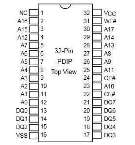
Except the AE29f2008-12 has one more address input than the AT28C256, is that right? Just checking.
Alright, we use A12 as the substitute for A15, and you say you attached A12 to the 6551. Did you also attach A12 to pin 3 of the inverter? (both changes as shown in the diagram upthread)
And can you also tell us please what assembler you're using. Also, what do you use to load the AE29f2008-12 with the file produced by the assembler? And what sort of file is it?
hitlp wrote:
I'm using the AE29f2008-12 which is a memory flash removed from a PC BIOS. The pinning is very similar to the AT28C256.
Quote:
since the 6507 only has addressing up to A12, I connected this port to 6551 as if it were the A15 of 6502.
And can you also tell us please what assembler you're using. Also, what do you use to load the AE29f2008-12 with the file produced by the assembler? And what sort of file is it?
In 1988 my 65C02 got six new registers and 44 new full-speed instructions!
https://laughtonelectronics.com/Arcana/ ... mmary.html
https://laughtonelectronics.com/Arcana/ ... mmary.html
Re: Writing in EEPROM and reading by 6502
Dr Jefyll wrote:
More questions. Sorry!
Quote:
Except the AE29f2008-12 has one more address input than the AT28C256, is that right? Just checking.
Quote:
Alright, we use A12 as the substitute for A15, and you say you attached A12 to the 6551. Did you also attach A12 to pin 3 of the inverter? (both changes as shown in the diagram upthread)
6507 Pin A12 -> 6551 Pin 3 CS1;
6507 Pin A12 -> SN74ls04n Pin 3;
SN74ls04n Pin 4 -> AE29f2008-12 Pin 22 CE#
SN74ls04n Pin 4 -> AE29f2008-12 Pin 24 OE#
Quote:
And can you also tell us please what assembler you're using. Also, what do you use to load the AE29f2008-12 with the file produced by the assembler? And what sort of file is it?
Code: Select all
SOURCES = kernel.s

%.o: %.s
        ca65 --cpu 6502 -o $@ -l $(@:.o=.lst) $<

all: kernel

kernel: $(SOURCES:.s=.o)
        cl65 --cpu 6502 -C kernel.cfg -t none -o $@ $^

clean:
        rm -f kernel *.o *.lst
- captura02.PNG (9.73 KiB) Viewed 1019 times
- captura03.PNG (3.79 KiB) Viewed 1019 times
Re: Writing in EEPROM and reading by 6502
The 6551 has /CS1 (active low) and CS0 (active high). Presumably you've tied CS0 high?
So you have an assembled object file. How is that getting into the ROM? And given that you have a 2KB address range mapped to the ROM, why is your image 8KB long?
So you have an assembled object file. How is that getting into the ROM? And given that you have a 2KB address range mapped to the ROM, why is your image 8KB long?
Re: Writing in EEPROM and reading by 6502
Chromatix wrote:
The 6551 has /CS1 (active low) and CS0 (active high). Presumably you've tied CS0 high?
Chromatix wrote:
So you have an assembled object file. How is that getting into the ROM? And given that you have a 2KB address range mapped to the ROM, why is your image 8KB long?
Re: Writing in EEPROM and reading by 6502
It does. So think about exactly what vector addresses it's reading, and what happens next.
Re: Writing in EEPROM and reading by 6502
You haven't answered all the questions, hitlp. What do you use to load the AE29f2008-12 flash ROM with the file produced by the assembler? I'd like to ensure that that tool is being directed properly -- that you're telling it to do the right thing.
In 1988 my 65C02 got six new registers and 44 new full-speed instructions!
https://laughtonelectronics.com/Arcana/ ... mmary.html
https://laughtonelectronics.com/Arcana/ ... mmary.html
Re: Writing in EEPROM and reading by 6502
Dr Jefyll wrote:
You haven't answered all the questions, hitlp. What do you use to load the AE29f2008-12 flash ROM with the file produced by the assembler? I'd like to ensure that that tool is being directed properly -- that you're telling it to do the right thing.
Re: Writing in EEPROM and reading by 6502
Hi guys,
I was thinking here, the 6502 processor has as the RESET VECTOR the address FFFC (1111 1111 1111 1100) and FFFD (1111 1111 1111 1101), both needing 16 bits for correct addressing?
Since 6507 has only 12 bits of address, it is correct to state that in this case, the RESET VECTOR would be the FFC addresses (1111 1111 1100) and FFD (1111 1111 1101)?
Re: Writing in EEPROM and reading by 6502
Right, the highest 4 bits are simply discarded before they reach the outside world, and the ROM will see them as whatever you've strapped them to. So again, think about where in the ROM the CPU will read its vectors from, and whether your image matches up with that. (Hint: it doesn't.)
Re: Writing in EEPROM and reading by 6502
Hello guys. It's me again.
I came back with a new 6502 processor and by the time I communicated with the ACIA (6551) it worked correctly. Now I'm trying to do a serial output with "Hello World!". I'm trying to use Putty but I do not see anything in the text output. Using the logic analyzer, every time I press the 6502 reset, it "spits" the same output. But I can not analyze it.
What can it be now?
- Attachments
-
- captura04.PNG (2.29 KiB) Viewed 833 times