B36502X Single Board Computer
- Individual_Solid
- Posts: 72
- Joined: 25 Jun 2021
- Location: Portland, Oregon, USA
- Contact:
Re: B36502X Single Board Computer
kernelthread wrote:
Regarding your schematic, note that whereas the RD strobe is active low, the WR strobe is active high. Data is latched on the falling edge of WR, so that needs to be coincident with the falling edge of the 6502 clock.
- GARTHWILSON
- Forum Moderator
- Posts: 8773
- Joined: 30 Aug 2002
- Location: Southern California
- Contact:
Re: B36502X Single Board Computer
You have a 74LS138 in the drawing for that. I don't know if you really intended to use 74LS, or if it's just that that was already in the CAD library; but the 74LS138 has a maximum propagation delay from your clock input to an output of 38ns. That's a lot, and adding a following inverter will only make it worse. If you use a '138, you might want one from a faster family. Otherwise I don't generally encourage use of the '138.
http://WilsonMinesCo.com/ lots of 6502 resources
The "second front page" is http://wilsonminesco.com/links.html .
What's an additional VIA among friends, anyhow?
The "second front page" is http://wilsonminesco.com/links.html .
What's an additional VIA among friends, anyhow?
- Individual_Solid
- Posts: 72
- Joined: 25 Jun 2021
- Location: Portland, Oregon, USA
- Contact:
Re: B36502X Single Board Computer
GARTHWILSON wrote:
You have a 74LS138 in the drawing for that. I don't know if you really intended to use 74LS, or if it's just that that was already in the CAD library; but the 74LS138 has a maximum propagation delay from your clock input to an output of 38ns. That's a lot, and adding a following inverter will only make it worse. If you use a '138, you might want one from a faster family. Otherwise I don't generally encourage use of the '138.
- Individual_Solid
- Posts: 72
- Joined: 25 Jun 2021
- Location: Portland, Oregon, USA
- Contact:
Re: B36502X Single Board Computer
Back to the main board -- It arrived, and it works!
I got the onboard CA1 LED blinking within a day. I initially soldered a can osc directly to the board and it was not clocking the CPU (no action on Sync or anything else). Once I pulled the can up and pushed a clock signal down the bus, we were in business. I'm not sure if the can was bad, or if I have a mistaken footprint for it. I'll further troubleshoot if it was the part or my design.
My 14-pin IDC sockets all went missing, so new ones are ordered and that will fill out the obvious missing bits of the board.
I do have a long list of minor layout adjustments to make before I spin a final "Version 1" but hopefully can draft that all up this week. I still need to dedicate the time to putting all the kicad files and their outputs on the web. I generated an interactive HTML BOM that makes assembly much easier.
- Individual_Solid
- Posts: 72
- Joined: 25 Jun 2021
- Location: Portland, Oregon, USA
- Contact:
Re: B36502X Single Board Computer
Oh, one thing of note. The Reset LED doesn't illuminate when the board is in /RESET. looking back at the schematic, it looks like I will have to solder it backward to give it a chance to illuminate! For the revision I will probably switch to using the last gate on the '00 to provide a RESET (high) signal.
EDIT: I never posted the schematic with the Reset LED I actually went with. Trust me, it was wrong.
- Individual_Solid
- Posts: 72
- Joined: 25 Jun 2021
- Location: Portland, Oregon, USA
- Contact:
Re: B36502X Single Board Computer
This is the reset LED circuit that was definitely never going to work:
Now, I had to try out of curiosity. I reversed the LED, so power would actually flow through the diode. For my first few tries, the LED worked as expected, it illuminated as the board was in RESET and turned off when activity on SYNC began. A few hours later, I returned to the board, and when connecting an LED (with a 3k resistor) from RESET->GND kept the board in RESET, presumably because it was pulling the line low? Does the resistor size matter here?
In either case, I will probably just do as described earlier, and use the last gate on the '00 to provide an active high reset signal.
Now on to the more...confusing behavior I'm noticing.
When I plug in the board, it takes nearly 7 seconds (that's right, not milli, but SECONDS) for the board to leave reset. I have removed the reset LED for this test. I've heard of an oscillator taking some time to start up but not on this order of magnitude. Unfortunately I will have to find my jewler's loupe to read the writing on the DS1813 to confirm if its the 5%/10%/15% variety. I'll also have to try some other power supplies.
- GARTHWILSON
- Forum Moderator
- Posts: 8773
- Joined: 30 Aug 2002
- Location: Southern California
- Contact:
Re: B36502X Single Board Computer
Individual_Solid wrote:
This is the reset LED circuit that was definitely never going to work:
http://WilsonMinesCo.com/ lots of 6502 resources
The "second front page" is http://wilsonminesco.com/links.html .
What's an additional VIA among friends, anyhow?
The "second front page" is http://wilsonminesco.com/links.html .
What's an additional VIA among friends, anyhow?
Re: B36502X Single Board Computer
Individual_Solid wrote:
This is the reset LED circuit that was definitely never going to work...
(EDIT: Yeah, Garth confirmed that it is correct. Thank you for destroying my self-confidence, Individual_Solid. :-))
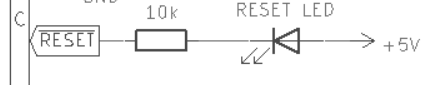
If I'm reading this right, the anode there is connected to +5V and the cathode through (a rather large!) resistor to /RESET, which is high when not asserted and low when asserted, which should cause current to flow from +5V through the LED to the grounded /RESET line. (Hopefully not pulling it up, per discussion below.)
Quote:
A few hours later, I returned to the board, and when connecting an LED (with a 3k resistor) from RESET->GND kept the board in RESET, presumably because it was pulling the line low? Does the resistor size matter here?
In your case I don't recall whether you have a separate pull-up for /RESET or if you're using the LED circuit as the pull-up as well. I would think that an additional separate pull-up might be a better idea since the LED circuit can only pull it up to 3.4 V or so due to the LED voltage drop, if I'm analyzing it correctly. And then you'll have to figure out how much current your LED+resistor is going to be sinking based the usual parallel resistance formula.
But you also, of course, need something that can sink all the current you're generating with the pull-up and the LED. You'll have to look at the data sheet for the part you're using for that to see what it does. I can't imagine you'd have any significant internal resistance in it since that would work against bringing the line all the way down to 0 V, but it's worth checking to see if you have accidentally ended up with some sort of resistor divider configuration.
You should also be able to simply use a jumper wire to short the RESET line to ground by hand. This isn't really recommended due to bounce and that at least on older CPUs you shouldn't hold reset down for too long, but it's worked for me on breadboards. If it's not, you can always just build another reset circuit on a breadboard, disconnect your existing one, and use the breadboard one to pull down reset.
And needless to say, put a 'scope on all this in case it's weird voltage levels that are doing odd stuff.
Quote:
When I plug in the board, it takes nearly 7 seconds (that's right, not milli, but SECONDS) for the board to leave reset.
Curt J. Sampson - github.com/0cjs
- Individual_Solid
- Posts: 72
- Joined: 25 Jun 2021
- Location: Portland, Oregon, USA
- Contact:
Re: B36502X Single Board Computer
GARTHWILSON wrote:
Individual_Solid wrote:
This is the reset LED circuit that was definitely never going to work:
Re: B36502X Single Board Computer
Just 'cause this reset light sounded like a neat idea, I wired up the same circuit to my RC6502 Apple 1 clone SBC† (schematic here). It's a 1.5K resistor (chosen by random grab into the "1K-3K" section of my parts box) from Vcc to the anode of a small random red LED, the cathode thence to /RESET. That's in parallel with the 1K (checked on the board) pull-up on /RESET.
It seems to work fine. The LED is lit for as long as I hold down the reset button (apparently the designer of this decided that just debounce, rather than a one-shot, was the way to go here) and goes out when I let it go. The levels look fine on the scope both around the falling edge and rising edge of the reset, and Wozmon appears to reset correctly and let me type in commands after.
The inverted configuration (LED reversed and non-/RESET end hooked to ground) was also briefly tested (not actually intentionally :-)) and also seemed to work, with of course the LED on when not in reset and off during reset.
So what you want to do there, with that original circuit above, has been shown work. I am guessing that it's something else in your setup.
__________
†Boy am I getting tired of typing all that out. Any suggestions for abbreviations? R6A1CSBC? Yeah, that's perfectly comprehensible.
Curt J. Sampson - github.com/0cjs
- Individual_Solid
- Posts: 72
- Joined: 25 Jun 2021
- Location: Portland, Oregon, USA
- Contact:
Re: B36502X Single Board Computer
cjs wrote:
Just 'cause this reset light sounded like a neat idea, I wired up the same circuit to my RC6502 Apple 1 clone SBC†
So what you want to do there, with that original circuit above, has been shown work. I am guessing that it's something else in your setup.
†Boy am I getting tired of typing all that out. Any suggestions for abbreviations? R6A1CSBC? Yeah, that's perfectly comprehensible.
So what you want to do there, with that original circuit above, has been shown work. I am guessing that it's something else in your setup.
†Boy am I getting tired of typing all that out. Any suggestions for abbreviations? R6A1CSBC? Yeah, that's perfectly comprehensible.
I had some time to do rework on the board last night (and the IDC connectors came from Mouser! still wish I knew where that first packet went). I placed a new reset LED on the board as originally drawn and it just worked.*
So, the remaining issue is that the board is held low in reset for over six (6!) seconds on initial power up. If this is a DS1813 with the 5% trip point, power needs to get to above 4.62V before coming out of reset. I suppose I should just put CLK, Reset, Sync, and "5V" (at the bus) on my scope and capture from flipping the power switch to watch what RESET is doing?
I can play around with power supplies, but this 5v supply I'm using has been pretty flawless with my last two builds. Though, if I want others to succeed with this board, its probably more efficient to put on a voltage regulator and expect a 9V supply (more common wall worts, it seems?)
* I think I should probably test LEDs when pulling them out of my parts bin, that first one must have been garbage.
Re: B36502X Single Board Computer
Individual_Solid wrote:
What is the reset circuit on the A1BEC (apple 1 bus extensible computer? Shrug!).
Anyway, it uses a standard 555 monostable multivibrator, or one-shot. (Schematic attached.) I was confused earlier about how it held reset low as long as you held the button (i.e., it has a minimum but not a maximum pulse width), but of course that's how a debouncer has to work, doh, as the switch may be bouncing as you hold it.
Quote:
So, the remaining issue is that the board is held low in reset for over six (6!) seconds on initial power up. If this is a DS1813 with the 5% trip point, power needs to get to above 4.62V before coming out of reset. I suppose I should just put CLK, Reset, Sync, and "5V" (at the bus) on my scope and capture from flipping the power switch to watch what RESET is doing?
Quote:
I can play around with power supplies, but this 5v supply I'm using has been pretty flawless with my last two builds. Though, if I want others to succeed with this board, its probably more efficient to put on a voltage regulator and expect a 9V supply (more common wall worts, it seems?)
My A1SBC (drawing about 280 mA because NMOS etc.) is actually powered by USB from my PC when not on the bus; the Arduino on it is powered by USB anyway, and there's a jumper to connect the Arduino board's USB power input to the main board's Vcc bus. I've worked on other stand-alone boards with multiple power inputs and regulators (e.g., a digital RGB to analogue RGB converter) and I've found that USB power is by far the most often used outside my workbench (and possibly even on it).
Curt J. Sampson - github.com/0cjs
- Individual_Solid
- Posts: 72
- Joined: 25 Jun 2021
- Location: Portland, Oregon, USA
- Contact:
Re: B36502X Single Board Computer
cjs wrote:
Quote:
So, the remaining issue is that the board is held low in reset for over six (6!) seconds on initial power up. If this is a DS1813 with the 5% trip point, power needs to get to above 4.62V before coming out of reset. I suppose I should just put CLK, Reset, Sync, and "5V" (at the bus) on my scope and capture from flipping the power switch to watch what RESET is doing?
[...] and I've found that USB power is by far the most often used outside my workbench (and possibly even on it).
I'm attaching some photos from an oscope trace of turning the board on. Due to the layout, it's not very easy for me to probe the pins directly on the DS1813. So, acknowledging that the SYNC will lag a few cycles behind leaving reset. On the trace, blue is the 5v supply, pink is SYNC, and yellow is RESET. This is all from the same power on, I've just zoomed a bit to show interesting things on the main trace.
At a high level. You can see 5v applied, a bunch of noise around the reset coming up, and then finally it makes it and we start syncing.
RESET starts to rise a few times but never makes it.
Actually, it makes it once...
This is a DS1813+10 so the typical trip point is 4.35V. It looks like the power source gets up to 5V pretty quickly, and doesn't dip back down.
Re: B36502X Single Board Computer
Well that's just a bit weird. Have you already pulled the reset LED out of the circuit to do this testing? That's the one thing there that's at all unusual. If so, I'd be tempted to lift the DS1813's reset pin and measure it independent of the rest of the circuit to see if there's something else in the circuit making it act weird.
Here's one idea about what might be going on. It's seems as if it would have to have some way to detect that something else on the line is bringing reset low so that it can detect the button press. And it would need to detect further presses and bounces during the 150 ms hold period after the button is released so that it could extend the hold, lest it later release and then a bunch of bounces toggle the reset line. (That's exactly the kind of thing this device is supposed to avoid, right?) So there might be something about that line, perhaps something drawing enough current in some subtle way, that the DS1813 thinks a button is being held down and so is holding things in reset until it's decided that the "button" is done bouncing.
Oh, and it might be useful even in the existing setup to zoom in on the power line 150 ms before /RESET is released to see if there's something going on there (such as very short drops in Vcc voltage) that you can't see at the wide zoom level.
Curt J. Sampson - github.com/0cjs
- Individual_Solid
- Posts: 72
- Joined: 25 Jun 2021
- Location: Portland, Oregon, USA
- Contact:
Re: B36502X Single Board Computer
cjs wrote:
Well that's just a bit weird. Have you already pulled the reset LED out of the circuit to do this testing? That's the one thing there that's at all unusual. If so, I'd be tempted to lift the DS1813's reset pin and measure it independent of the rest of the circuit to see if there's something else in the circuit making it act weird.
It all works. The leads on the original DS1813 are long enough to be resoldered into another board. Perhaps I damaged it when originally constructing, but I'll give it another try at life. I'd feel pretty unlucky if I had a bad LED and a bad DS1813 on the reset circuit of this build, but crazier things have happened...
In any case, that means this revision has fully come to life. and the LED/Key boards arrived fully assembled from JLC yesterday, so once the 14 pin IDC cables arrive, it'll be time to give that board a test.