Chips are seated! Kind of a nightmare with the cheap sockets (from amazon, yikes) I had in my kit. I'm going to investigate a better part (that is, I'm going to see what Jameco sells as I'm usually happy with their stock).
Something is wrong with IO Port A, it won't power my logic tester. IO Port B gave a satisfactory +5V and GND for the pen to light up (test number 1...). I visually inspected my soldering job and its not the best ever but I don't see anything obvious that would explain why I can't just get simple power out. I'm going to have to come back to it with fresh eyes.
I've already made a number of silly mistakes along the way, and definitely want to update the silkscreen to include things like ... chip name instead of just U1/U2 etc. Additionally, at the very least I'd like to have 5v and GND more obviously indicated for each chip.
I'll be troubleshooting more in the morning. No questions at this time, but wanted to share the progress.
The F-1 (aka "I Was Too Excited to Draft the UART Circuit")
-
Individual_Solid

- Posts: 72
- Joined: 25 Jun 2021
- Location: Portland, Oregon, USA
- Contact:
-
BigDumbDinosaur

- Posts: 9428
- Joined: 28 May 2009
- Location: Midwestern USA (JB Pritzker’s dystopia)
- Contact:
Re: The F-1 (aka "I Was Too Excited to Draft the UART Circui
Dr Jefyll wrote:
For polarity "protection," I just include a suitably beefy Schottky diode on the board, wired in parallel with the supply so the wall wart sees a short if I accidentally reverse the connections.
You could put a big electrolytic across the power input in place of the diode and wait for results when you accidentally reverse-polarize the power.
x86? We ain't got no x86. We don't NEED no stinking x86!
-
BigDumbDinosaur
- Posts: 9428
- Joined: 28 May 2009
- Location: Midwestern USA (JB Pritzker’s dystopia)
- Contact:
Re: The F-1 (aka "I Was Too Excited to Draft the UART Circui
Individual_Solid wrote:
Chips are seated! Kind of a nightmare with the cheap sockets (from amazon, yikes) I had in my kit. I'm going to investigate a better part (that is, I'm going to see what Jameco sells as I'm usually happy with their stock).
Caveat emptor when purchasing electronic parts from Amazon, eBay et al.
Quote:
Something is wrong with IO Port A, it won't power my logic tester.
From where did you purchase this chip?
Quote:
I've already made a number of silly mistakes along the way, and definitely want to update the silkscreen to include things like ... chip name instead of just U1/U2 etc. Additionally, at the very least I'd like to have 5v and GND more obviously indicated for each chip.
When I build a unit, I print an enlarged copy of the PCB and make notes on it as to which part goes where, plus I highlight the VCC connections in red and ground connections in green. On PCB layouts, it's customary for pin 1 to be a square pad rather than round, which is a further aid to getting parts correctly installed.
x86? We ain't got no x86. We don't NEED no stinking x86!
-
Individual_Solid
- Posts: 72
- Joined: 25 Jun 2021
- Location: Portland, Oregon, USA
- Contact:
Re: The F-1 (aka "I Was Too Excited to Draft the UART Circui
Last night I had some time to sit down and troubleshoot more efficiently. I made some progress, but not the best in the world.
Once chips were seated, I initially tried to get my LCD printing "Hello World". It worked first try! just kidding. No, it did not. The LCD powered up but didn't initialize, let alone write Hello World. Time to take a step back and see whats working and whats not.
First, I spent a lot of time making sure that each VIA out pin was properly connected to the expansion header, and that the expansion header was properly wired to each LCD pin. I had made a few mistakes manually wiring, and, rather tragically, a few of the header pins aren't providing a super stable power line. I looked more closely at my solder job, and I definitely rushed (or just didn't properly attach) the headers. I was using 1x40 female headers that I snapped, taped into place, and soldered on. The joints are a little weak and the headers are lifted off the board more than I want. BDD - this is what I meant by my IO Port having issues, not the chip but my poorly hacked together physical connector/port.
Despite this, I decided to keep debugging with my $20 sparkfun logic analyzer. I switched to a simple program that loads $#50 into the ORB of my VIA and then ror, store to ORB, loop ad naseum. I'm honestly not sure how best to use PulseView to do logic debugging. My guess is that I should use a 1Mhz sample rate (my clock rate) but I don't know if that's actually a valid idea. Once I added a few NOPS in the loop and the reset, I was able to start visibly seeing lines from the VIA go on and off. However, I would frequently lose one or more channels worth of information (they'd randomly pull high or low and stay there). When I have everything laid out perfectly flat, nothing underneath, no wires in weird bends, things pushed in very far, I mostly get clear lines, but still see some noise.
Now I know some of this is due to my cheap logic analyzer, messy desk, loose dupont connects, etc... But I honestly do believe a lot of this may be due to the rushed job I did soldering the board together. It was still 84degrees Farenheit indoors when I pulled out the soldering iron.
So, I could keep troubleshooting RevASer1... But today the Jameco box came-high quality sockets and fresh resistors and caps. real IDC connectors and 2x07 shrouded headers instead of cheap snapped off headers. Even a DC barrel jack that I can shove onto the footprint of my terminal block connector.
So my thinking for this long weekend is to construct a second of the RevA boards. That way, I'll have a better "known quantity" to work from. But here's the differences:
I've been thinking a lot about the goals of my board. As someone else mentioned, I'm working backward. From Elements of Computing Systems to Rodnay Zaks. I don't feel compelled to keep my board "period accurate" but I also appreciate the creativity that can emerge from constraints. That's why I'm still considering learning how to use the 6551 even if it's just going to talk to a pi pico that does the rest of what I want. Well, OTOH I just got some of Geoff's VT100 terminal kits mailed from Tindie, so maybe I should go full on RS232.
In any case, here's my list of priorities/next steps
Once chips were seated, I initially tried to get my LCD printing "Hello World". It worked first try! just kidding. No, it did not. The LCD powered up but didn't initialize, let alone write Hello World. Time to take a step back and see whats working and whats not.
First, I spent a lot of time making sure that each VIA out pin was properly connected to the expansion header, and that the expansion header was properly wired to each LCD pin. I had made a few mistakes manually wiring, and, rather tragically, a few of the header pins aren't providing a super stable power line. I looked more closely at my solder job, and I definitely rushed (or just didn't properly attach) the headers. I was using 1x40 female headers that I snapped, taped into place, and soldered on. The joints are a little weak and the headers are lifted off the board more than I want. BDD - this is what I meant by my IO Port having issues, not the chip but my poorly hacked together physical connector/port.
Despite this, I decided to keep debugging with my $20 sparkfun logic analyzer. I switched to a simple program that loads $#50 into the ORB of my VIA and then ror, store to ORB, loop ad naseum. I'm honestly not sure how best to use PulseView to do logic debugging. My guess is that I should use a 1Mhz sample rate (my clock rate) but I don't know if that's actually a valid idea. Once I added a few NOPS in the loop and the reset, I was able to start visibly seeing lines from the VIA go on and off. However, I would frequently lose one or more channels worth of information (they'd randomly pull high or low and stay there). When I have everything laid out perfectly flat, nothing underneath, no wires in weird bends, things pushed in very far, I mostly get clear lines, but still see some noise.
Now I know some of this is due to my cheap logic analyzer, messy desk, loose dupont connects, etc... But I honestly do believe a lot of this may be due to the rushed job I did soldering the board together. It was still 84degrees Farenheit indoors when I pulled out the soldering iron.
So, I could keep troubleshooting RevASer1... But today the Jameco box came-high quality sockets and fresh resistors and caps. real IDC connectors and 2x07 shrouded headers instead of cheap snapped off headers. Even a DC barrel jack that I can shove onto the footprint of my terminal block connector.
So my thinking for this long weekend is to construct a second of the RevA boards. That way, I'll have a better "known quantity" to work from. But here's the differences:
- Mise-en-place. After cleaning up my desk space, I want to build a workspace laid out specifically for the board construction. That means not balancing things on top of books. That means all the parts in a little kit box organized and laid out for the project.
- Reference materials. As BDD suggested (thank you!), I'd like to print out a schematic and board layout to have to reference while building. Important pins are highlighted. Chip names and component values are included. This will ensure I only have to socket each chip once! I already have the datasheets for the WDC chips printed out, put in full page plastic protectors, and bindered up. This makes it super easy to flip to a pin out or register layout and see whats needed. I will print and binder at least the pinout page for the rest of the components on the board. All this (including schematic, layout, BOM) can go in the final binder.
- Quality sockets, quality construction. I'm going to use the new good Jameco parts and take my time to carefully attach components. Not trying to solder any joints with the board vertical. Similarly, take my time while socketing chips.
- Physically I'm using male shrouded headers instead of female headers for the IO Ports. And a DC Barrel jack for power instead of terminal blocks.
- As mentioned earlier, decoupling caps and power traces in general need some love
- Lots of board footprint only changes, for cap sizes, headers, and more
- Silkscreen around the IO Ports (including standardizing on IO(X)P(Y) where X is the VIA's number (1 or 2) and Y is the port on the VIA (A or B). Will also switch to clockwise pinout instead of odd-even. Also silkscreen needs to label +5 and GND on all the ports
- mounting holes drilled in the four corners, for standoffs at the very least.
- Add LED indicators for Power, SYNC, and RESETB. (consider test points as well)
- Maybe add a UART, maybe not yet
 I'm leaning toward an SPI UART driven by a VIA, but I _am_ interested in learning the 6551 programming model.
I've been thinking a lot about the goals of my board. As someone else mentioned, I'm working backward. From Elements of Computing Systems to Rodnay Zaks. I don't feel compelled to keep my board "period accurate" but I also appreciate the creativity that can emerge from constraints. That's why I'm still considering learning how to use the 6551 even if it's just going to talk to a pi pico that does the rest of what I want. Well, OTOH I just got some of Geoff's VT100 terminal kits mailed from Tindie, so maybe I should go full on RS232.
In any case, here's my list of priorities/next steps
- Construct RevAB2 with my notes above and more attention to detail. Hopefully get it doing something obvious on the logic analyzer so we can move forward to LEDs and then an LCD.
- Design RevB (to use a very similar BOM).

Re: The F-1 (aka "I Was Too Excited to Draft the UART Circui
As noted by several commenters in the 6502 PCB Power On Issues thread these LCD displays are often very fussy indeed about how they are started up. So, they are a great peripheral for a computer design which works, but not a great one to use as a proof of life: an LED is about as simple as things get, for that. (Indeed, flashing an LED is very commonly used as a first project with a platform.)
-
Individual_Solid
- Posts: 72
- Joined: 25 Jun 2021
- Location: Portland, Oregon, USA
- Contact:
Re: The F-1 (aka "I Was Too Excited to Draft the UART Circui
BigEd wrote:
As noted by several commenters in the 6502 PCB Power On Issues thread these LCD displays are often very fussy indeed about how they are started up. So, they are a great peripheral for a computer design which works, but not a great one to use as a proof of life: an LED is about as simple as things get, for that. (Indeed, flashing an LED is very commonly used as a first project with a platform.)
-
GARTHWILSON

- Forum Moderator
- Posts: 8775
- Joined: 30 Aug 2002
- Location: Southern California
- Contact:
Re: The F-1 (aka "I Was Too Excited to Draft the UART Circui
Individual_Solid wrote:
That means not balancing things on top of books. That means all the parts in a little kit box organized and laid out for the project.
Quote:
Physically I'm using male shrouded headers instead of female headers for the IO Ports.
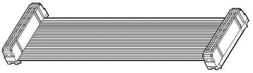
Yes; standard is to have the male on the board, so you can plug IDCs onto it. IDCs (insulation-displacement connectors) are super easy to mount onto ribbon cable. You just put the IDC over the cable and mash it on with a vise, resulting in this:
Quote:
Silkscreen around the IO Ports (including standardizing on IO(X)P(Y) where X is the VIA's number (1 or 2) and Y is the port on the VIA (A or B). Will also switch to clockwise pinout instead of odd-even.
The standard pinout, looking down into the pins on the board is like this
- pinHeaderPinNumbering.gif (9.37 KiB) Viewed 1521 times
so the numbers go in order of the conductors in a ribbon cable that plugs onto it, and pin 2 is always at the top right, regardless of how many pins there are.
Quote:
Maybe add a UART, maybe not yet I'm leaning toward an SPI UART driven by a VIA
I like the MAX3100. The MAX3110 is the same thing with line drivers and receivers built in. These ICs come in small skinny DIPs which save a lot of board space, compared to wide 24- or 28-pin UARTs plus line drivers and receivers.
Quote:
I do have a question about decoupling caps. I see you mentioned not all MLCC are made the same. I've been buying ceramic disc caps (0.1uF) from Jameco for about $.15c per. The MLCC you linked from Mouser is about 45c per. I found ceramic disc caps on Mouser, but they were well over a dollar, sometimes $4. They had much higher voltage ratings. Am I missing an obvious listing for something in the sub-20c range thats a good enough 0.1uF cap? Otherwise I'll just keep snapping up the Jameco part that I already know well.
If you're using thru-hole only, they should look something like this:
- monolithicCeramicCap.jpg (11.22 KiB) Viewed 1521 times
Solder it with just barely enough lead length to prevent breaking if it gets bumped. The leads add inductance which you'll want to minimize. If you can solder SMT chip capacitors down to the board (which is pretty easy if you stay with at least 0805 size), so much the better, for good AC performance.
http://WilsonMinesCo.com/ lots of 6502 resources
The "second front page" is http://wilsonminesco.com/links.html .
What's an additional VIA among friends, anyhow?
The "second front page" is http://wilsonminesco.com/links.html .
What's an additional VIA among friends, anyhow?
-
BigDumbDinosaur
- Posts: 9428
- Joined: 28 May 2009
- Location: Midwestern USA (JB Pritzker’s dystopia)
- Contact:
Re: The F-1 (aka "I Was Too Excited to Draft the UART Circui
GARTHWILSON wrote:
Individual_Solid wrote:
Physically I'm using male shrouded headers instead of female headers for the IO Ports.
One time, I got carried away with using the bench vise in my metal-working shop to attach a 50-pin IDC connector to a SCSI cable I was making—and did literally mash it. Man, was I peeved, as it was the last 50-pin connector I had in my parts supply.
x86? We ain't got no x86. We don't NEED no stinking x86!
-
Individual_Solid
- Posts: 72
- Joined: 25 Jun 2021
- Location: Portland, Oregon, USA
- Contact:
Re: The F-1 (aka "I Was Too Excited to Draft the UART Circui
GARTHWILSON wrote:
Darn! I'm doomed! Well, at least my workbench isn't quite as messy as Jim ____'s (I can't remember his last name, but he was an industry guru), shown at viewtopic.php?p=27948#p27948 ! LOL My construction and my source code are super neat, but not my workbench. You'll notice I've never posted a picture of my workbench. In fact, that's one of my hesitations about posting a video!
Quote:
Yes; standard is to have the male on the board, so you can plug IDCs onto it. IDCs (insulation-displacement connectors) are super easy to mount onto ribbon cable.
Quote:
The standard pinout, looking down into the pins on the board is like this
so the numbers go in order of the conductors in a ribbon cable that plugs onto it, and pin 2 is always at the top right, regardless of how many pins there are.
Quote:
If you're using thru-hole only, they should look something like this:
Solder it with just barely enough lead length to prevent breaking if it gets bumped. The leads add inductance which you'll want to minimize. If you can solder SMT chip capacitors down to the board (which is pretty easy if you stay with at least 0805 size), so much the better, for good AC performance.
-
GARTHWILSON
- Forum Moderator
- Posts: 8775
- Joined: 30 Aug 2002
- Location: Southern California
- Contact:
Re: The F-1 (aka "I Was Too Excited to Draft the UART Circui
Quote:
One time, I got carried away with using the bench vise in my metal-working shop to attach a 50-pin IDC connector to a SCSI cable I was making—and did literally mash it. Man, was I peeved, as it was the last 50-pin connector I had in my parts supply. 
http://WilsonMinesCo.com/ lots of 6502 resources
The "second front page" is http://wilsonminesco.com/links.html .
What's an additional VIA among friends, anyhow?
The "second front page" is http://wilsonminesco.com/links.html .
What's an additional VIA among friends, anyhow?
-
GARTHWILSON
- Forum Moderator
- Posts: 8775
- Joined: 30 Aug 2002
- Location: Southern California
- Contact:
Re: The F-1 (aka "I Was Too Excited to Draft the UART Circui
Individual_Solid wrote:
Is that an MLCC or a Ceramic Disc? I guess my real question is, and I don't even know if this is a question that can be answered.... what sort of price should I be paying PER capacitor (I can do currency conversion, but I'm in the NW USA) for a simple 0.1uF filter cap?
http://WilsonMinesCo.com/ lots of 6502 resources
The "second front page" is http://wilsonminesco.com/links.html .
What's an additional VIA among friends, anyhow?
The "second front page" is http://wilsonminesco.com/links.html .
What's an additional VIA among friends, anyhow?
-
Individual_Solid
- Posts: 72
- Joined: 25 Jun 2021
- Location: Portland, Oregon, USA
- Contact:
Re: The F-1 (aka "I Was Too Excited to Draft the UART Circui
For the next revision, I may try JLCPCB's pick n place assembly and plop surface mount caps, resistors, LEDs, etc... on the board, and do the chips/sockets/connectors (through hole stuff) myself. I could certainly do that (simple) surface mount stuff on my own, but my kit of passives is pretty much all through hole, so if I have to buy the components anyway I may try their cool ability to plop those right on board before shipping to me! I haven't researched the economies of scale yet, but it seems like for their "basic parts" catalog (which looks to have what I need in terms of passives) I can get away without paying too much more. I'll have to do the math.
Thanks for the details on caps. It's great to hear what real people have on their parts list.
Thanks for the details on caps. It's great to hear what real people have on their parts list.
-
floobydust

- Posts: 1394
- Joined: 05 Mar 2013
Re: The F-1 (aka "I Was Too Excited to Draft the UART Circui
GARTHWILSON wrote:
Individual_Solid wrote:
That means not balancing things on top of books. That means all the parts in a little kit box organized and laid out for the project.
I believe that was Jim Williams...
https://www.edn.com/jim-williams-contributions-to-edn/
Regards, KM
https://github.com/floobydust
https://github.com/floobydust
-
Individual_Solid
- Posts: 72
- Joined: 25 Jun 2021
- Location: Portland, Oregon, USA
- Contact:
Re: The F-1 (aka "I Was Too Excited to Draft the UART Circui
I assembled a second board using sockets from Jameco, and wow, it really did make a difference. Very minor struggle seating the ICs, no pins got bent in weird ways.
But, alas, getting the output I want from my '22 isn't seeming to be happening. I temporarily gave up on the cheapo logic analyzer and wired up LEDs (with current limiting resistors) to the PB outs. Even with the following very simple program, I get no actual output on PB of the '22. I was using a blinking program, but tried to minimize it as much as possible just to see a pattern.
My next step is to go pin-to-pin with the continuity tester and see if anything is obviously wrong.
But, alas, getting the output I want from my '22 isn't seeming to be happening. I temporarily gave up on the cheapo logic analyzer and wired up LEDs (with current limiting resistors) to the PB outs. Even with the following very simple program, I get no actual output on PB of the '22. I was using a blinking program, but tried to minimize it as much as possible just to see a pattern.
Code: Select all
  .org $8000

reset:
  lda #%11111111
  sta $6002
  lda #%10100101
  sta $6000


  .org $fffc
  .word reset
  .word $0000
-
Individual_Solid
- Posts: 72
- Joined: 25 Jun 2021
- Location: Portland, Oregon, USA
- Contact:
Re: The F-1 (aka "I Was Too Excited to Draft the UART Circui
I'll note, the logic analyzer did indicate that the reset signal is working at least. I get a whole bunch of nonsense on PB2 lines when I'm analyzing at 2MHz, multiple pins are bouncing all over the place. But when I depress the reset button, all my lines go low. At least something works!