Amazing PET haul! Help identifying some oddballs.

Let's talk about anything related to the 6502 microprocessor.
User avatar
Oneironaut
Posts: 734
Joined: 25 May 2015
Location: Gillies, Ontario, Canada
Contact:

Re: Amazing PET haul! Help identifying some oddballs.

Post by Oneironaut »

After some testing with various DAC amplifiers, I have determined that analog input into the PET Monitor is not very good.

Image

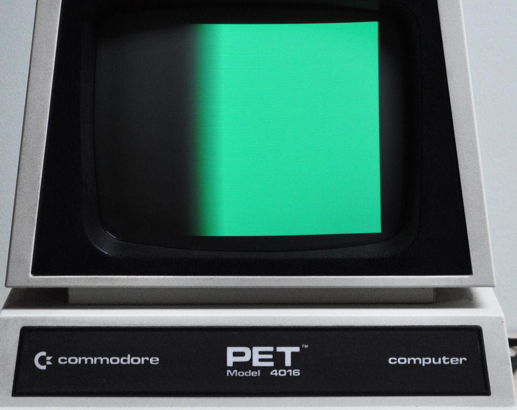
The pattern should fade from black to full green, but instead transitions quickly at about 40 percent.
Fixing this would require changing the actual video drive circuitry, and I won't go that far.

So I guess if I do any kind of GFX board, it will be like the others... high resolution and single shade (digital).
I did test a 720 pixel dot map though, and this Monitor is certainly capable of displaying crisp pixels.
Might try a horizontal resolution of 1024 next, but for that I need a faster microcontroller!

One interesting thing I noted though is if I feed the original PET pixel stream back into the tapped point shown in the last photo, the resulting video is just as good, possibly a little sharper.

Knowing how Commodore would shave every single part from a board, I am surprised that they left 2 extra transistors and a bunch of other passives that seem to do nothing!

Ok, that's it for this thread.

Cheers,
Radical Brad
User avatar
barrym95838
Posts: 2056
Joined: 30 Jun 2013
Location: Sacramento, CA, USA

Re: Amazing PET haul! Help identifying some oddballs.

Post by barrym95838 »

I think I can discern about seven different shades there, which is better than two, but might not have a favorable cost/benefit ratio.
Got a kilobyte lying fallow in your 65xx's memory map? Sprinkle some VTL02C on it and see how it grows on you!

Mike B. (about me) (learning how to github)
User avatar
BigEd
Posts: 11464
Joined: 11 Dec 2008
Location: England
Contact:

Re: Amazing PET haul! Help identifying some oddballs.

Post by BigEd »

Indeed, I was thinking a suitable circuit could produce values in the sensitive range. Or indeed a suitable look up table ahead of a DAC with enough output levels.
User avatar
Dr Jefyll
Posts: 3526
Joined: 11 Dec 2009
Location: Ontario, Canada
Contact:

Re: Amazing PET haul! Help identifying some oddballs.

Post by Dr Jefyll »

BigEd wrote:
a suitable circuit could produce values in the sensitive range.
I had the same thought, and I don't think you'd need anything fancy. Unless I'm missing something you could do the trick with just a resistor or two (or a trimpot) to attenuate the signal coming out of your DAC, then another resistor/trimpot to apply a suitable fixed, DC offset. Admittedly, you probably won't get 256 discernable shades. But, as Mike noted, you'd be better off than with just two.

Fun project!

-- Jeff

Edit: What would be a reasonable number of shades to shoot for -- sixteen? If direct-mapping the 16 values results in poor linearity then Ed's suggestion of a lookup table may bear consideration. (Of course this assumes a DAC whose input is wider than 4 bits.)
Last edited by Dr Jefyll on Mon Aug 03, 2020 4:32 pm, edited 1 time in total.
In 1988 my 65C02 got six new registers and 44 new full-speed instructions!
https://laughtonelectronics.com/Arcana/ ... mmary.html
User avatar
Oneironaut
Posts: 734
Joined: 25 May 2015
Location: Gillies, Ontario, Canada
Contact:

Re: Amazing PET haul! Help identifying some oddballs.

Post by Oneironaut »

I was thinking about workin' that "narrow band", but it also suffers from blurry edges.
I know it's not the DAC as I use the same design to drive 800x600 VGA at 40MHz, and here I am only pushing 10MHz.

For my next experiment, I am going to see if the PET Monitor will allow double fast horizontal scanning. Currently, I am pushing out 20KHz scan lines at 60Hz, so I am going to try either 40KHz lines at 60Hz or 40Hz.

The reason is to attempt a 1024 X 512 pixels display, which would also allow images to be displayed using dithering.

As for memory requirements of the GFX addon board, it almost works out the same anyhow...

- 360 X 200 with 8 bit pixels = 72K frame buffer
- 1024 X 512 with 1 bit pixels = 64K frame buffer

There are also some advantages to resolution over shades, especially with finely drawn lines and characters.

I will continue this thread and report back my attempts to force the Monitor into a higher scan rate.
I am assuming here that that is how the 80 column PETs did it?

Later.
Brad
User avatar
floobydust
Posts: 1394
Joined: 05 Mar 2013

Re: Amazing PET haul! Help identifying some oddballs.

Post by floobydust »

As the older CRTs have a 4:3 aspect ratio, a 1024 x 512 pixel screen wouldn't display images correctly (non-square pixels) resulting in a vertically squashed image. Perhaps a 768 x 576 pixel screen might be possible within the range of the display? Unless of course, you plan on changing the images beyond dithering to correct the aspect. Just a thought...
User avatar
Oneironaut
Posts: 734
Joined: 25 May 2015
Location: Gillies, Ontario, Canada
Contact:

Re: Amazing PET haul! Help identifying some oddballs.

Post by Oneironaut »

Good point, thanks.

I just rejigged my AVR code to put out 40KHz @ 60 FPS, and the PET Monitor locked on just fine, so it can handle the double scan rate.

With 768 pixels, this puts the Dot Clock at a nice 40MHz, which is also well within the speed of a 74164 shift register. Since I intend to make my GFX expander form age-appropriate logic parts, this works out nicely.

I will probably shorten the blanking periods and shoot for 800 * 480, which will put the image into the overscan, resulting in no borders and a "safe" video zone of 768 * 400 visible pixels.

Now that I have a basic plan, I will continue a new thread when I can.

Cheers!
Brad

floobydust wrote:
As the older CRTs have a 4:3 aspect ratio, a 1024 x 512 pixel screen wouldn't display images correctly (non-square pixels) resulting in a vertically squashed image. Perhaps a 768 x 576 pixel screen might be possible within the range of the display? Unless of course, you plan on changing the images beyond dithering to correct the aspect. Just a thought...
fachat
Posts: 1124
Joined: 05 Jul 2005
Location: near Heidelberg, Germany
Contact:

Re: Amazing PET haul! Help identifying some oddballs.

Post by fachat »

btw, there is a project to re-build the SuperPET here: https://github.com/nils-eilers/uMMF
Author of the GeckOS multitasking operating system, the usb65 stack, designer of the Micro-PET and many more 6502 content: http://6502.org/users/andre/
shoggoth
Posts: 8
Joined: 05 Mar 2018

Re: Amazing PET haul! Help identifying some oddballs.

Post by shoggoth »

You could add an analog gamma adjustment circuit after your DAC output, that may smooth out your gradients enough.

You could also use an op amp to change the output range of the DAC output so that the low and high map into the middle useful portion of the full voltage range you're using now

EDIT - the fuzzy edge part is going to be capacitance at the point you're injecting the signal right? So if you can put out a low impedance signal (a DAC probably won't do that, but an op amp would, but you'd need to be wary of oscillation driving a capacitive load) you should get crisper edges
fachat
Posts: 1124
Joined: 05 Jul 2005
Location: near Heidelberg, Germany
Contact:

Re: Amazing PET haul! Help identifying some oddballs.

Post by fachat »

Oneironaut wrote:
Good point, thanks.

I just rejigged my AVR code to put out 40KHz @ 60 FPS, and the PET Monitor locked on just fine, so it can handle the double scan rate.
You did what? Wow. I'm impressed.

So that busts the assumption that a much faster horizontal sync could be the cause for the monitor dying with the "killer poke" (that has been debunked already for a different reason).

That opens a lot of possibilities for new hardware projects!

However, I think we need to make sure we understand which one of the monitor revisions are capable of doing this. I understand this is a 12" monitor, are you sure the 321448 schematics are the right ones? Do you understand why this actually works? For example, I would have expected the horizontal slope to be constant, so a horizontal sync that comes twice as often would result in a horizontal line of just half the width... (but I'm not good enough in electronics for that)

Thanks
André
Author of the GeckOS multitasking operating system, the usb65 stack, designer of the Micro-PET and many more 6502 content: http://6502.org/users/andre/
Post Reply