6502.org Forum  Projects  Code  Documents  Tools  Forum
It is currently Fri Nov 22, 2024 7:33 am

All times are UTC


Post new topic Reply to topic  [ 581 posts ]  Go to page Previous  1 ... 22, 23, 24, 25, 26, 27, 28 ... 39  Next
Author Message
PostPosted: Thu Apr 09, 2020 11:26 pm 
Offline
User avatar

Joined: Tue Mar 05, 2013 4:31 am
Posts: 1385
Interesting... or in the words of Spock, fascinating.

I've also found that chips from the same manufacturer can exhibit differences when you crank up the clock. I have over a dozen SCC2691 DIPs, some marked as Philips, others as NXP. All run perfectly fine at 6MHz on my C02-Pocket SBC. I have only one that runs perfectly fine at 8MHz... not a great result for that many chips, but alas, it's one chip that exceeds the specs by a decent margin. The rogue that runs at 8MHz is an older Philips.

I also have a few of the newer NXP DUARTs... including an NXP 28L92 and a couple of the Exar versions of the NXP 26C92. Also, note that TI are now offering their version of the 28L92 but only in a quad flat-pack package, hence SMT only. I'm thinking I should put a PLCC-44 socket on a small and get it wired into the expansion connector on my C02-Pocket SBC. By getting an NXP DUART connected, I should be able to get it running with a minor BIOS change to replace the SCC2691... running a single UART. I was hoping that the 28L92 would survive beyond 14MHz (future SBC design).

Looking forward to your next change to support the 28L92.

_________________
Regards, KM
https://github.com/floobydust


Top
 Profile  
Reply with quote  
PostPosted: Fri Apr 10, 2020 12:42 am 
Offline
User avatar

Joined: Thu May 28, 2009 9:46 pm
Posts: 8505
Location: Midwestern USA
floobydust wrote:
Interesting... or in the words of Spock, fascinating.

Good old Spock. However, Uhura was more...er...fascinating. :P

Quote:
I've also found that chips from the same manufacturer can exhibit differences when you crank up the clock.

That's to be expected, considering that minor process variations from wafer to wafer will occur.

Quote:
The rogue that runs at 8MHz is an older Philips.

It's been quite a while since Phillips divested themselves of what is now NXP. It wouldn't surprise me to learn that NXP changed foundries after the divesture as a cost-cutting move. In chip fabrication, as in everything else, you get what you pay for.

Quote:
I also have a few of the newer NXP DUARTs... including an NXP 28L92 and a couple of the Exar versions of the NXP 26C92.

I seem to recall noting in the past that there are some subtle differences between the Exar clones and the genuine NXP devices. They weren't a deal breaker, just something of which to be aware.

The 26C92 is a slightly dumbed-down version of the 28L92. Timing specs are a little slower and the FIFO's are only 8-deep. I briefly ran POC V1.1 on a 26C92 and then went with the 28L92 because of its deeper FIFOs.

Quote:
I was hoping that the 28L92 would survive beyond 14MHz (future SBC design).

Looking forward to your next change to support the 28L92.

I'm cogitating as we speak (so to speak) on how to test wait-stating with the DUART. I'm starting to think I need to add some logic so a wait-state can be initiated for any I/O access, as I also have to account for the SCSI host adapter and its requirements.

_________________
x86?  We ain't got no x86.  We don't NEED no stinking x86!


Top
 Profile  
Reply with quote  
PostPosted: Sat Apr 11, 2020 10:02 pm 
Offline
User avatar

Joined: Thu May 28, 2009 9:46 pm
Posts: 8505
Location: Midwestern USA
BigDumbDinosaur wrote:
For some time, we've been kicking around various methods of wait-stating when a slow device must be accessed on an otherwise-fast machine...

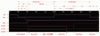
While I had the logic analyzer (LA) hooked up I captured what the '816 was doing during a read cycle and annotated the result. Operating conditions are room temperature, 5 volts and Ø2 at 12.5 MHz. The transition from logic 0 to logic 1 is assumed to occur at 2.5 volts and is assumed to be symmetric—the LA has no provisions for independently setting the logic 0 and logic 1 levels. Annotated times are in nanoseconds, with a ±2ns accuracy.

Attachment:
File comment: 65C816 Read Cycle — Selected Signals
data_bus_turnaround_scaled.gif
data_bus_turnaround_scaled.gif [ 295.58 KiB | Viewed 29196 times ]

The code that was being executed during this capture was:

Code:
         sep #%00110000        ;8-bit registers
         lda #%00000011        ;read...
         pha                   ;from...
         plb                   ;bank $03
;
loop     lda $8000             ;effectively LDA $038000
         bra loop

Prior to starting this, I placed $04 at location $8000 so as to produce a data bus pattern that would clearly not be the same as the bank address. The capture occurs at the final cycle of the LDA $8000 instruction, which is when the '816 reads the addressed location. As is always the case with the '816, the Ø2 low phase is when address setup occurs and the bank bits are emitted on the data bus.

Of particular note is the bank address persistence after the rise of Ø2. The measured 14ns is critical because the bank latch must be closed before that period expires, otherwise undefined content may be latched and ultimately result in data corruption due to addressing errors. Assuming the use of a 74AC573, there is only a 3-4ns margin, worst-case, before the data bus turnaround begins. That being the case, the reference circuit shown on page 44 in the 65C816 data sheet would fail if the '573 is at the weak end of its specifications. This would be due to the fact that the inverted Ø2 signal used to control the latch will lag Ø2 by one gate delay, effectively reducing the 14ns window by anywhere from 2ns to 7ns, depending on the inverter being used.

Also, note the 8ns period between when the '816 stops emitting the bank and the addressed device (RAM, in this case) puts data on the bus. In my POC designs, the Ø2-qualified read/write circuit drives /RD low one gate delay after the rise of Ø2, which ranges from 1.9ns to 6.6ns, according to the data sheet. Assuming the gate's performance falls near the middle of the spec, it would mean the RAM is responding with considerable alacrity to /RD.

The 8ns data persistence after the fall of Ø2 can be attributed to a combination of logic latency and bus capacitance.

_________________
x86?  We ain't got no x86.  We don't NEED no stinking x86!


Top
 Profile  
Reply with quote  
PostPosted: Sun Apr 12, 2020 12:25 am 
Offline

Joined: Mon May 21, 2018 8:09 pm
Posts: 1462
Hmm - and what if, instead of deriving the bank gate from an inverted Phi2, you derive Phi2 as an inverted Phi1? That would give you more margin for the latch event.


Top
 Profile  
Reply with quote  
PostPosted: Sun Apr 12, 2020 1:40 am 
Offline
User avatar

Joined: Thu May 28, 2009 9:46 pm
Posts: 8505
Location: Midwestern USA
Chromatix wrote:
Hmm - and what if, instead of deriving the bank gate from an inverted Phi2, you derive Phi2 as an inverted Phi1? That would give you more margin for the latch event.

Just to clarify for the benefit of anyone who is not sure what it is we're discussing, it's the tBH parameter in Jeff's drawn-to-scale timing diagram. This is the amount of time the '816 continues to drive the bank bits onto the data bus after the rise of Ø2.

I foresee two problems if Ø1 is made to lead Ø2. The first one is tBH would be improved at the expense of tBAS. As the MPU's timings are independent of Ø2 frequency at any given voltage, the effective shortening of tBAS may violate the latch's setup time before Ø2 goes high if the frequency is ramped up enough.

The second problem is the bank latch will be opened prior to the completion of the data cycle. If that happens soon enough before the fall of Ø2 the data bus' contents will end up in the latch and cause A16-A21 to assume an undefined state. That will assuredly cause data corruption and likely crash the machine.

In a system that generates Ø2 from a flop, the Q and /Q outputs are exactly 180° out of phase. So if Q is Ø2 then /Q would be Ø1, eliminating the need for the inverter. I think as long as the inverter's delay can be eliminated and the latch's performance is 3 to 4ns better than tBH the timing margin will be reliably maintained.

In the case of the clock stretcher circuit describe a few posts back, there is no complement to the counter's output, which means either an inverter must be used to generate Ø1 or the counter's output has to be run through a flop to generate the out-of-phase clocks. Doing the latter would mean the clock oscillator would have to run at four times the frequency of Ø2. Doing the former would put us right back into that potential timing quagmire involving tBH.

_________________
x86?  We ain't got no x86.  We don't NEED no stinking x86!


Top
 Profile  
Reply with quote  
PostPosted: Sun Apr 12, 2020 8:01 am 
Offline
User avatar

Joined: Thu Dec 11, 2008 1:28 pm
Posts: 10985
Location: England
Thanks for the measurements and timing diagram, BDD. That's valuable. It would be great to see it in a new head post, or tagged onto a thread about '816 bus timings (if there is one.)


Top
 Profile  
Reply with quote  
PostPosted: Sun Apr 12, 2020 10:50 am 
Offline
User avatar

Joined: Sat Dec 01, 2018 1:53 pm
Posts: 730
Location: Tokyo, Japan
cjs wrote:
BigDumbDinosaur wrote:
Instead of RDY, V1.2 will wait-state by stretching Ø2 when a slow access is needed. With WDC MPUs, Ø2 can be stopped in either phase without causing trouble. In this particular case, Ø2 will be halted in the high phase for one or two clock cycles when a wait-state is required.... As a bonus, this trickery will work with any CMOS 6502, since any of them may be stopped in the same fashion without issue.

Would this work with NMOS 6502s as well, assuming the stretch was kept to a few clock-cycles duration?

I've never seen figures for the 6502, but I do seem to recall reading a spec somewhere for the 6800 and/or 6809 that the chip could not lose internal state so long as you didn't stall the clock for more than 160 microseconds or something like that.

Well, I now have seen figures for the 6502. Follow the link for details; the TLDR is, "offical figures vary and can be wrong; five to six microseconds has been shown to be safe."

_________________
Curt J. Sampson - github.com/0cjs


Top
 Profile  
Reply with quote  
PostPosted: Sun Apr 12, 2020 11:46 am 
Offline
User avatar

Joined: Thu Dec 11, 2008 1:28 pm
Posts: 10985
Location: England
Very interesting, good link. Another thing which is probably worth its own thread!
> New 6502s can be stopped for 40 microseconds, but they deteriorate...
> The data sheets are inconsistent. Synertek says 40 microseconds, Rockwell says 10 microseconds, and MOS Technology doesn't say at all.
> I'd stick with five or six.


Top
 Profile  
Reply with quote  
 Post subject: POC Computer Version One
PostPosted: Sun Apr 12, 2020 1:24 pm 
Offline

Joined: Thu Apr 19, 2018 12:53 pm
Posts: 25
What would happen if Q1 were to be used to trigger the latch and an inverted Q1 to act as Q2?
Will this meet the timing specs?

BR/
Guus


Top
 Profile  
Reply with quote  
PostPosted: Sun Apr 12, 2020 3:10 pm 
Offline
User avatar

Joined: Thu May 28, 2009 9:46 pm
Posts: 8505
Location: Midwestern USA
Guus Assmann wrote:
What would happen if Q1 were to be used to trigger the latch and an inverted Q1 to act as Q2?
Will this meet the timing specs?

I'm confused. To which Q1 are you referring?

_________________
x86?  We ain't got no x86.  We don't NEED no stinking x86!


Top
 Profile  
Reply with quote  
PostPosted: Sun Apr 12, 2020 3:46 pm 
Offline
User avatar

Joined: Thu Dec 11, 2008 1:28 pm
Posts: 10985
Location: England
That would surely be phi1 and phi2.


Top
 Profile  
Reply with quote  
PostPosted: Sun Apr 12, 2020 3:58 pm 
Offline
User avatar

Joined: Fri Dec 11, 2009 3:50 pm
Posts: 3367
Location: Ontario, Canada
Now will be a good time for a schematic. :) Can you confirm these details, please, BDD? The drawing below is taken from my original post. Details not pertinent to POC (such as the non-stretched VIA clock) have been removed, and I added some notations that do relate to the POC context. Also shown are two inverters, one which theoretically would drive the enable input of '573 latch (for the Bank Address) and another (in red) which I included only for the sake of discussion.

This '163 circuit replaces the 'AC74 in BDD's PDF schematic, included in this post.


Attachments:
stretcher options .png
stretcher options .png [ 11.21 KiB | Viewed 29057 times ]

_________________
In 1988 my 65C02 got six new registers and 44 new full-speed instructions!
https://laughtonelectronics.com/Arcana/ ... mmary.html


Last edited by Dr Jefyll on Tue Apr 21, 2020 2:23 am, edited 2 times in total.
Top
 Profile  
Reply with quote  
PostPosted: Sun Apr 12, 2020 4:44 pm 
Offline
User avatar

Joined: Fri Dec 11, 2009 3:50 pm
Posts: 3367
Location: Ontario, Canada
BigDumbDinosaur wrote:
there is no complement to the counter's output,
Correct.

Quote:
[...] which means either an inverter must be used to generate Ø1 or the counter's output has to be run through a flop to generate the out-of-phase clocks.
There are other options, and they're tolerably easy and satisfactory. I need to make an addendum to my original post, but it probably won't happen today.

_________________
In 1988 my 65C02 got six new registers and 44 new full-speed instructions!
https://laughtonelectronics.com/Arcana/ ... mmary.html


Top
 Profile  
Reply with quote  
PostPosted: Sun Apr 12, 2020 4:48 pm 
Offline
User avatar

Joined: Fri Dec 11, 2009 3:50 pm
Posts: 3367
Location: Ontario, Canada
BigDumbDinosaur wrote:
In a system that generates Ø2 from a flop, the Q and /Q outputs are exactly 180° out of phase.
I used to believe this, but it turns out not to be a reliable assumption. Some modern flipflops are implemented using CMOS Transmission Gates rather than a symmetrical arrangement of cross-coupled NAND's as in the old days.

The 'AHC74 accomplishes the "edge triggered" function by using one follow-hold transparent latch that feeds into another (arranged as hold-follow). Each latch has two TG's feeding its input, acting as a SPDT switch to select new data or previously stored data. (diagram below)

In the second stage, notice how the path from the input node to Q is one gate-delay shorter than the path from the input node to /Q. This casts doubt on the theory that transitions on the Q and /Q outputs will be exactly simultaneous.

It's true that data sheets don't always faithfully indicate internal logic. Sometimes a warning to that effect appears. But the assumption about Q and /Q switching exactly simultaneously is clearly out the window, IMO.

The data sheet doesn't support assumptions; all it tells us is the min and max clock-to-output delays. Q's delay will fall within that range and so will /Q's. But nothing says Q's place within the range will exactly match /Q's.

-- Jeff


Attachments:
flipflop internals.png
flipflop internals.png [ 17.51 KiB | Viewed 29127 times ]

_________________
In 1988 my 65C02 got six new registers and 44 new full-speed instructions!
https://laughtonelectronics.com/Arcana/ ... mmary.html


Last edited by Dr Jefyll on Sun Apr 12, 2020 5:58 pm, edited 1 time in total.
Top
 Profile  
Reply with quote  
PostPosted: Sun Apr 12, 2020 5:56 pm 
Offline
User avatar

Joined: Thu May 28, 2009 9:46 pm
Posts: 8505
Location: Midwestern USA
BigEd wrote:
That would surely be phi1 and phi2.

I don't know. None of my schematics make a reference to a Q1.

_________________
x86?  We ain't got no x86.  We don't NEED no stinking x86!


Top
 Profile  
Reply with quote  
Display posts from previous:  Sort by  
Post new topic Reply to topic  [ 581 posts ]  Go to page Previous  1 ... 22, 23, 24, 25, 26, 27, 28 ... 39  Next

All times are UTC


Who is online

Users browsing this forum: No registered users and 29 guests


You cannot post new topics in this forum
You cannot reply to topics in this forum
You cannot edit your posts in this forum
You cannot delete your posts in this forum
You cannot post attachments in this forum

Search for:
Jump to: