Hi, i'm newbie here and i would like to ask about the feasibility of my idea. Looking at some youtube videos, i stumbled upon various 6502 based systems from single board computers to breadboard based ones (thanks to Ben Eater) and started thinking about making something similar, since when i was a kid, i had a Commodore 64 and i was familiar with the assembly instruction set and the programming of the various peripherials. My idea is that instead of building a single board computer or using wire wrap or a breadboard, i would like use a simple passive backplane with around 8 sockets and build each component on its own card. The idea is to have a cpu card, ram and rom cards and various i/o cards i can build later. The first version would have a power, clock and reset logic card, a cpu card with the dip socketed WDC65C02, 32KB ram at 0KB, 16KB eeprom at 48KB and enough free slots to add 5 i/o cards (like 2 joystick ports and a bunch of leds, serial i/o, an lcd and maybe later video out).
My question is if i use a WDC65C02 cpu and try to stick to 5V CMOS components only and plan to run only at around 1 or 2 MHz, then can i get this system to reliably work if i use a hand soldered raster stripboard backplane (15x10 cm in size) with 8 dual row sockets (all pins doubled for mechanical stability) and hand soldered stripboards with dual row connector pins, some bare jumper wires and ic sockets for the cards? If this could be made to work, then what common mistakes should i look out for?
Thanks: Viktor
Building a passive backplane based expandable system

Re: Building a passive backplane based expandable system
There's no reason it can't work - and you may want to look at the S100 bus system and for a more modern take on that, the RC2014 project (although these are primarily 8080/Z80 systems, there are some 6502 boards too)
And go back to the old Apple II - while the CPU and RAM was on the mother board, there were 8 expansion slots for various peripherals from disk drives to printers to video to process control, etc. (also note that the Northstar Horizon was a Z80, S100 system, but they also put the CPU and serial IO on the motherboard as well as the slots for the memory, disk, etc.)
Also see here, http://65xx.unet.bz/index.php although not much has changed on it for some time.
Good luck!
-Gordon
--
Gordon Henderson.
See my Ruby 6502 and 65816 SBC projects here: https://projects.drogon.net/ruby/
Gordon Henderson.
See my Ruby 6502 and 65816 SBC projects here: https://projects.drogon.net/ruby/
Re: Building a passive backplane based expandable system
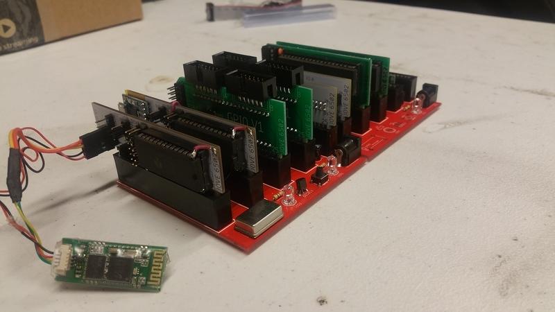
This is almost exactly how my SBC was designed and built. PCB was produced with clock and reset circuitry, everything else is on little cards connected by 50 pin edge connectors.
Also by not populating certain components I was able to daisy chain two backplanes together for 8 available slots.
The contraption runs stable at 4mhz for weeks or months at a time.
EDIT: Sorry for the giant image, copy/pasted the linked (raw) image from my gallery instead of the normal sizes image.
-
GARTHWILSON

- Forum Moderator
- Posts: 8775
- Joined: 30 Aug 2002
- Location: Southern California
- Contact:
Re: Building a passive backplane based expandable system
If you go small like thedrip shows above, it'll work fine. You should at least keep the clock generation on the same board with the processor though, really close to it, not on a separate board. Otherwise, I don't recommend putting the processor's own buses on the backplane. See the "Expansion Buses and Interfaces" section of the 6502 primer.
http://WilsonMinesCo.com/ lots of 6502 resources
The "second front page" is http://wilsonminesco.com/links.html .
What's an additional VIA among friends, anyhow?
The "second front page" is http://wilsonminesco.com/links.html .
What's an additional VIA among friends, anyhow?
Re: Building a passive backplane based expandable system
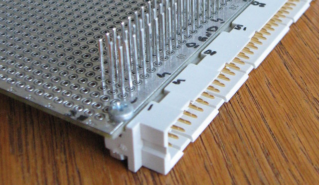
I did a 4 slot, hand wired, backplane for my Acorn Atom project details & pictures are on the forum at:viewtopic.php?f=3&t=5728
it's currently running with a 10mhz clock.
it's currently running with a 10mhz clock.

Re: Building a passive backplane based expandable system
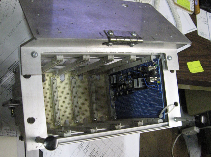
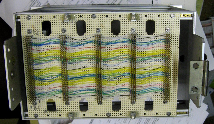
I've done one too, but it's a bit different than your concept.
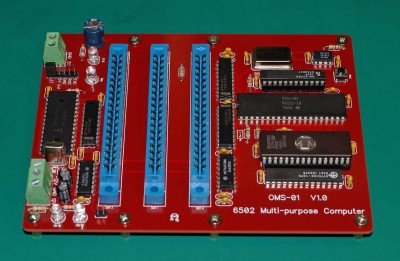
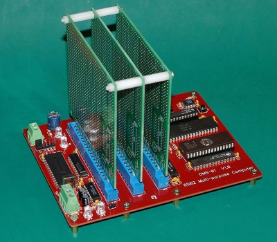
There are actually 4 'slots' on the bus (well, 5 if you include the CPU section). The last one is taken up with the chips on the left in the pictures which include an UART and a latch for system control. This one runs nicely at 16MHz. The bus is buffered from the CPU section which is home to the CPU, clock, glue and all memory. The secret is to keep things compact.
I'm also working on a 4 slot backplane for use with OSI 600 series computers. It's based on the machine above and will use the same pin-out and addressing scheme so that boards I develop can be used on either system.
Bill
Re: Building a passive backplane based expandable system
1) if the connectors can still be sourced I will suggest the board mounted connector used for the Atari 7800 game console, memory serves it has everything needed to interface RAM/ROM to a 6502, including some additional IO pins for audio and system clock.
2) IMHO the 16 bit IBM PC AT connector seems appealing, there are passive backplain boards available that fit in modern ATX computer cases. (if ISA standards are adhered to the existing expansion cards could be used.)
2) IMHO the 16 bit IBM PC AT connector seems appealing, there are passive backplain boards available that fit in modern ATX computer cases. (if ISA standards are adhered to the existing expansion cards could be used.)

Re: Building a passive backplane based expandable system
The RC6502 Apple I Replica is done in exactly this way, with even with the clock on a separate board. (I've not used it myself, but I do have the SBC version also from that repo and it seems to work pretty well. The 150 ns rise time on the Φ2 output makes me a bit nervous, but others have told me that's pretty normal.)
You might even consider just using his backplane board and any boards you happen to be interested in, and wiring up your own for whichever parts you want to do.
You might even consider just using his backplane board and any boards you happen to be interested in, and wiring up your own for whichever parts you want to do.
Curt J. Sampson - github.com/0cjs
Re: Building a passive backplane based expandable system
something I've been considering is the use of 72 pin SIMM sockets used for DRAM years ago, the sockets are still readily available for reasonable cost. in my specific case I am interested in the ability to easily change out processor types connected to my FPGA project. the other thing I am keeping in mind is the mounting hole pattern for ATX PC cases, they are already commodity products so I intend to use them.
-
BigDumbDinosaur

- Posts: 9428
- Joined: 28 May 2009
- Location: Midwestern USA (JB Pritzker’s dystopia)
- Contact:
Re: Building a passive backplane based expandable system
N2- wrote:
something I've been considering is the use of 72 pin SIMM sockets used for DRAM years ago, the sockets are still readily available for reasonable cost. in my specific case I am interested in the ability to easily change out processor types connected to my FPGA project. the other thing I am keeping in mind is the mounting hole pattern for ATX PC cases, they are already commodity products so I intend to use them.
x86? We ain't got no x86. We don't NEED no stinking x86!
Re: Building a passive backplane based expandable system
BigDumbDinosaur wrote:
N2- wrote:
something I've been considering is the use of 72 pin SIMM sockets used for DRAM years ago, the sockets are still readily available for reasonable cost. in my specific case I am interested in the ability to easily change out processor types connected to my FPGA project. the other thing I am keeping in mind is the mounting hole pattern for ATX PC cases, they are already commodity products so I intend to use them.
Re: Building a passive backplane based expandable system
BigDumbDinosaur wrote:
PCI sockets are also readily available and easier to work with.
And it also occurs to me that PCI uses card-edge connectors for the cards, which makes life difficult for prototyping because you need custom protoboard, rather than any old protoboard you have lying around.
I think that DIN 41612 looks a lot more promising, if one's going to go for a "real" connector. It's on 0.1" centers, and so goes straight into protoboard, it's got KiCAD footprints available (at least for the 2-row versions), and it seems fairly cheap (2×32 is under $2/connector on AliExpress). I notice that the 3×32 version of the connector is used for the RetroBrew (ex-N8VEM) ECB (EuroCard Bus); they provide CAD files for a nice little 3-slot passive backplane.
Curt J. Sampson - github.com/0cjs
-
GARTHWILSON
- Forum Moderator
- Posts: 8775
- Joined: 30 Aug 2002
- Location: Southern California
- Contact:
Re: Building a passive backplane based expandable system
cjs wrote:
it also occurs to me that PCI uses card-edge connectors for the cards, which makes life difficult for prototyping because you need custom protoboard, rather than any old protoboard you have lying around.
Quote:
I think that DIN 41612 looks a lot more promising, if one's going to go for a "real" connector. It's on 0.1" centers, and so goes straight into protoboard
http://WilsonMinesCo.com/ lots of 6502 resources
The "second front page" is http://wilsonminesco.com/links.html .
What's an additional VIA among friends, anyhow?
The "second front page" is http://wilsonminesco.com/links.html .
What's an additional VIA among friends, anyhow?
Re: Building a passive backplane based expandable system
VME bus chassis are based on the euro card format, while a poor example I have a 3 card version of this style chassis I paid $50 for about 10 years ago. https://www.ebay.com/itm/Elma-32VS-VME- ... 4017416779
the bonus to using this type of VME bus is that it's already setup for the Motorola 68k, 16 bit bus with 24 address lines.
the bonus to using this type of VME bus is that it's already setup for the Motorola 68k, 16 bit bus with 24 address lines.
Re: Building a passive backplane based expandable system
kvp wrote:
My question is if i use a WDC65C02 cpu and try to stick to 5V CMOS components only and plan to run only at around 1 or 2 MHz, then can i get this system to reliably work if i use a hand soldered raster stripboard backplane (15x10 cm in size) with 8 dual row sockets (all pins doubled for mechanical stability) and hand soldered stripboards with dual row connector pins, some bare jumper wires and ic sockets for the cards? If this could be made to work, then what common mistakes should i look out for?
Thanks: Viktor
Thanks: Viktor
Bill