
I think, if you can give up on cycle-accurate behaviour, a clean datapath with enough registers should be able to deliver all of those instruction sets. But usually performance or fidelity gets the high priority, and then you end up being forced to make something rather like the original - which means, matching three originals will be quite complex.
I would say though that a good instruction test suite would be a necessity, because there will be so many little cases of how to handle flags and so on.
The very first project in my working life was an 8 bit datapath machine to emulate 8051 and other (unspecified) instruction sets. Like many other projects, it was cancelled. But I did get to attend some 8051 training. Of course, my role was very minor indeed. I remember there was a dual-port register file.
TTL 6502 Here I come

Re: TTL 6502 Here I come
Had my share of 80537 C and assembly coding back in 1998.
It's fun, when the design team of a company had jumped ship,
and you have to bake their "leftovers" together for building a reliable product.
But about the idea of supporting non_6502 instruction sets with a 6502 related TTL CPU:
Wouldn't it be fun to run a non_6502 operating system (which is able to handle file systems) inside a 64KB partition,
and then making function calls to it from a 6502\6510 C64 environment or such ?
Re: TTL 6502 Here I come
Started another thread about how to build a faster 6502 TTL CPU here.

Re: TTL 6502 Here I come
Here now, finally, are the schematics for the C74-6502.
Truth be told, I had wanted to wait until these were made final before posting. But given the various requests I've received, I decided to relent and put these up in this "not quite finished" state. The attached schematics do accurately reflect the existing prototype, and are annotated to clearly indicate with the various patches that were applied during debugging. I have attached also an accompanying PCB Patch Guide detailing all such patches as an aid to anyone wishing to build a working unit from the prototype boards (we already have one such project underway!).
Although work remains before we can officially call an end to this project, I did want to take a moment and say thanks on behalf of Team C74. What an incredible adventure this has been! I am very grateful to all here who supported these efforts with such enthusiasm and interest. It's a wonderful privilege to be part of this community.
And of course, a special thanks also to the rest of Team C74 -- ttlworks and Dr Jefyll -- for their generous help and friendship.
... But there is no rest for the weary, as already work has started on a potential successor to the C74-6502. Can it be made faster still? Stay tuned ...
Notes to the schematics:
Card A Schematic -- Page 1
Card A Schematic -- Page 2
Card A Schematic -- Page 3
Card B Schematic -- Page 1
Card B Schematic -- Page 2
Card C Schematic -- Page 1 (Unannotated)
Card C Schematic -- Page 2 (Unannotated)
Truth be told, I had wanted to wait until these were made final before posting. But given the various requests I've received, I decided to relent and put these up in this "not quite finished" state. The attached schematics do accurately reflect the existing prototype, and are annotated to clearly indicate with the various patches that were applied during debugging. I have attached also an accompanying PCB Patch Guide detailing all such patches as an aid to anyone wishing to build a working unit from the prototype boards (we already have one such project underway!).
Although work remains before we can officially call an end to this project, I did want to take a moment and say thanks on behalf of Team C74. What an incredible adventure this has been! I am very grateful to all here who supported these efforts with such enthusiasm and interest. It's a wonderful privilege to be part of this community.
And of course, a special thanks also to the rest of Team C74 -- ttlworks and Dr Jefyll -- for their generous help and friendship.
... But there is no rest for the weary, as already work has started on a potential successor to the C74-6502. Can it be made faster still? Stay tuned ...
Notes to the schematics:
- The annotated schematics are large files -- regrettably that had to be the case to make them legible.
- I did not complete annotated schematics for Card C (K24 card). There are a couple of patches for this card outlined in the Patch Guide.
- The K24 SPI circuitry remains untested at this point. All other functions in the K24 Card work as advertised.
- I will in time post Gerbers, BOMs and Eagle files on the project website. In the meantime, please PM me if you are interested.
C74-6502 Website: https://c74project.com

Re: TTL 6502 Here I come
Drass wrote:
I decided to relent and put these up in this "not quite finished" state.]
Re: TTL 6502 Here I come
joanlluch wrote:
Hi Drass, I just realised you posted this here one week ago, so thanks for sharing!
Happy to share!
I’m enjoying following your build over at anycpu.org. It’s going to different, given that you are building a more RISCy CPU, but I certainly hope the schematics prove useful. Let me know if you have any questions. I’d be glad to help out.
Best,
Drass
C74-6502 Website: https://c74project.com
Re: TTL 6502 Here I come
The talk I gave at WoC 2018 on the C74-6502 is now up on YouTube. This was a wonderful day, made better by the fact that Dr Jefyll and I were able to exhibit together at the event. Here is a write-up on the day (posted upthread).
Thanks to the WoC folks for accommodating Jeff and I at the last minute, and for hosting such a great event.
Here is a link to a video of the talk: https://youtu.be/dB3P5tt4gnE
Thanks to the WoC folks for accommodating Jeff and I at the last minute, and for hosting such a great event.
Here is a link to a video of the talk: https://youtu.be/dB3P5tt4gnE
- Attachments
-
Last edited by Drass on Sat Dec 07, 2019 1:34 pm, edited 1 time in total.
C74-6502 Website: https://c74project.com
Re: TTL 6502 Here I come
Magnificent!

Re: TTL 6502 Here I come
Really Great 
Thank You Drass!
Thank You Drass!

Re: TTL 6502 Here I come
Drass wrote:
Here is a link to a video of the talk:
-
SpottedGal
- Posts: 19
- Joined: 15 Dec 2019
Re: TTL 6502 Here I come
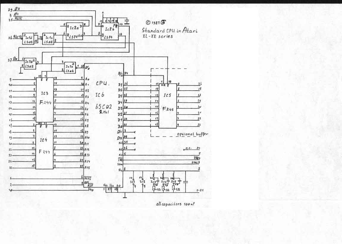
I was wondering if you had any plans to add the "Sally" mod to the 6502. That would make it compatible with Atari 8-bit computers. The Ataris use the ANTIC chip as a part of the architecture, which is the graphics coprocessor and DMA controller. On stock Ataris, Antic also drives the RAM refresh. In homebrew Atari clones, RAM refresh is unnecessary since they use SRAM. Anyway, Antic has a halt line to pause the 6502 while accessing the memory. The original Atari 8-bit computers added 4 chips to pause the 6502 and disconnect the 6502 from the memory, allowing Antic to directly read the memory (and allow "Freddy" and the MMU chips write access for refresh). However, they soon got MOS to release a modified 6502 which included a /Halt line in place of one of the N/C leads. So that simplified the motherboard (or CPU card) layout.
If you use the "Sally" 6502 in a machine not built around it, you would notice no difference. The CPU stays active and operates as a normal 6502. However, if you use a regular 6502 in one built around the "Sally," memory corruption is bound to occur. Likely nothing would read or write where expected since competition would occur on the address lines.
Interestingly, the Intel x86 and compatible chips do this too. They have a halt line so the DMA controller (or northbridge) can have competition-free access to the memory.
Taking this further, someone could implement this in FPGA (with the "Sally" mod) and install it on a 40-pin adaptor board. They could go as far as to include an oscillator on the adaptor and a 3-pin jumper to select either the clock on the motherboard or the one on the socket board. Then the CPU could use its own clock while letting the motherboard use the original clock, thus allowing Antic, GTIA, Pokey, and PIA to work properly while the CPU is boosted.
Last edited by SpottedGal on Sun Dec 15, 2019 11:55 pm, edited 1 time in total.
Re: TTL 6502 Here I come
Welcome! That's an interesting idea and an interesting historical note. We know that Atari had transistor-level schematics for the 6502 (and I think the instruction decoder differs in detail from the usual one, even if the behaviour is the same) so maybe they designed the variation themselves. Here's an informative thread. And here's another. "Atari got the license from Rockwell to use it's design, and they added the /Halt logic, also buffering the address and data buses so it'll go into "High Z" or high-impedance mode when halted. This makes it possible for Antic to take over those buses fully."
-
SpottedGal
- Posts: 19
- Joined: 15 Dec 2019
Re: TTL 6502 Here I come
Thanks for the welcome. I'll check that out. I was unaware of the Rockwell connection. I heard it was MOS who did the mod for them.
The politics around that were interesting. Jack Tramiel worked for Commodore. He was upset that TI was increasing the price of ICs that competitors were using, so Commodore bought out MOS to ensure they'd keep their supplier. Then Tramiel moved to Atari. Diehard Atari fans weren't the fondest of him since he was around when they got out of the computer business. He was the one who was largely responsible for the price wars that hurt all the smaller computer companies of that era. After he acquired MOS, he greatly undercut TI, apparently out of spite. That not only hurt TI, and Commodore for that matter, but Atari, Timex-Sinclair, Coleco, and others. By the time it was over, I think you could get a TI-99-4A for about $70 or so (though most of those were likely the vendor-locked version 3 with the membrane keyboard).
I imagine the Sally mod is easier to do inside the CPU than external on the board like the earliest Atari computers did. I'm not sure what all is needed. Obviously, tri-state buffers on the data and address pins would be needed, and you might need a transistor to disconnect the clock from the program counter. I'm not sure if any sync circuitry would be needed.
---
While here, there are at least 2 interesting homebrew Ataris. One is the 1088 XEL. It uses the 5 main Atari chips (Sally, Antic, Pokey, GTIA, and PIA), and an extra Pokey for stereo sound. There were quad Pokeys back in the day too (and likely FPGA-based replacements today to keep vintage arcade games working). It uses SRAM instead of DRAM, so it doesn't use the Freddy or MMU chips. It adds a PS/2 keyboard controller and the Mousetari chip. The motherboard has no ROM socket, but it does have sockets for the Ultra 1 meg board which has an upgraded Atari ROM to allow access to 1088K (and likely other features such as faster I/O and the ability to use DS/DD floppies). The beauty of this design is full Atari compatibility. It can take the other 3rd-party mods to allow for use with more modern video hardware. The Antic upgrade will work with it which will allow CGA/RGB monitors to work, and with more modes and a sharper picture, though only standard modes will go to the motherboard's GTIA. The cores in that mod could be upgraded and a crystal changed to work on some VGA monitors (but missing a sync signal, so not 100% compatible). There's also a piggyback GTIA board called Sophia, and the latest version of that supports DVI (and you can derive VGA and HDMI from that). That's easier to use and cleaner than having to add a sync doubler to the RGB.
There's also the Eclaire. It implements most of the Atari on an FPGA. The FPGA has Sally 6502, Antic, 2 Pokeys, GTIA, and PIA on it, as well as perhaps some RAM/ROM. It's made to work with PS/2 mouse and keyboard too. It has no 65816 support, but it can clock its 6502 to about 50 Mhz. That is mostly a prototype, though you could contact the developer and if enough are interested, he might order a batch, and that's a more affordable option than the 1088 XEL. It's not as upgradeable as the 1088 XEL, but it already has most of the available upgrades in the FPGA. I think I'd rather see Drass' 6502 be converted to FPGA and used in that project since there's 65816 support. If it were on FGPA with the other chips, that would likely eliminate any need to multiplex the 8 additional address lines on the data lines, if you want the 16 Mb support. The 65816 multiplexes the top address byte with the data lines so it will fit in a 40-pin DIP.
There are other 6502-based Atari compatible machines out there, but they are not as interesting as the above 2. There is the Mist (and also a Mister) which emulates most of the older machines in FPGA but has the disadvantage of not being able to use vintage peripherals or 3rd-party upgrades. So compatibility is limited.
Last edited by SpottedGal on Mon Dec 30, 2019 6:21 am, edited 2 times in total.
Re: TTL 6502 Here I come
Welcome.
The C74-6502 CPU aims for 6510 compatibility, so it already has three state outputs for address, data, R/W.
On the 6502 connectors, BE (6502 pin 36) is the high active output enable for these buffers.
//6502 and 6510 have different pin assignments, so C74-6502 has two sets of connectors for supporting both chips.
From the schematic in the atariage forum, one just would have to add a 7402 and a 7474 to the C74-6502 CPU.
But at higher clock speeds C74-6502 CPU uses a CY2302 zero delay buffer in the clock circuitry, and that chip doesn't like clock skewing tricks.
So for a "Sally" modification like in that schematic, one has to go without the zero delay buffer, what might limit the CPU clock speed to 12MHz or so.
Internally, the C74-6502 CPU architecture is different from the 6502 chip.
The program counter is a register, not a counter.
And I don't know what side effects tinkering with the register write enable would have because C74-6502 is pipelined.
I don't have the most recent version of the C74-6502 CPU layouts and schematics at hand, but it looks like there isn't much space left on the PCBs.
Maybe Drass could provide some more info.
Re: TTL 6502 Here I come
You’re right Dieter. Gating the clock input to the C74-6502 will require that the Zero-Delay-Buffer be bypassed. That can be done with a solder jumper, but it will limit the clock-rate to about 14MHz.
As for space, there is none! Having said that, I often found creative ways to repurpose what is on the board already. There’s is a lot of functionality there, so I would not be surprised if there is a way to shake loose a gate and a flip-flop by disabling some unneeded feature or other.
As for space, there is none! Having said that, I often found creative ways to repurpose what is on the board already. There’s is a lot of functionality there, so I would not be surprised if there is a way to shake loose a gate and a flip-flop by disabling some unneeded feature or other.
C74-6502 Website: https://c74project.com