Since we are at it:
D04 passively snooped the 6502 bus for write cycles into the address range $0400..$07FF
(it internally had 32kB of display RAM).
If there was such a CPU write, it kept data and address from the 6502 bus in latches,
then updated the D04 internal display RAM in the right moment (1MB/sec write throughput).
The 6502 only does consecutive write cycles when responding to an interrupt, and does this to $01xx.
// For the 65816, it's different.
For the 6502 the worst case scenario outside the stack area would be code like:
STA $0400
STA $0401
What causes three CPU read cycles followed by one CPU write cycle.
So it was possible to run the 6502 at 3 MHz. (At 4 MHz, some characters didn't make it from CPU to display memory.)
CPU and D04 were running at different clock speeds, generated from different oscillators.
(The D04 bus interface was sort of a kludge, because back then I didn't know as much about 6502
bus timing as I know now. You better build that part different.)
Unfortunately, for the C64 this trick won't work, because it causes a compatibility problem
if the VIC-II can't read $0000..$01FF. I think I had mentioned this somewhere at the start
of the thread when talking about system integration.
So in a C64 this means there would be consecutive write cycles to the display memory,
and to compensate for this one would have to us more than one set of latches between CPU and display RAM...
or FIFOs... or to use dual port RAM as display RAM.
;---
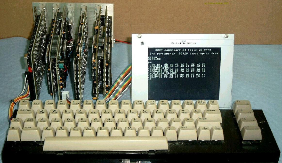
D04 was monochrome, but it was able to display 40*25 text and something like 320*200 hires
at the same time, pixels were mixed together by using XOR gates.
BTW: in theory, it would be possible to have more than just one display controller of that sort on a 6502 bus.
...But enough of these old stories. Will be back next Monday.

