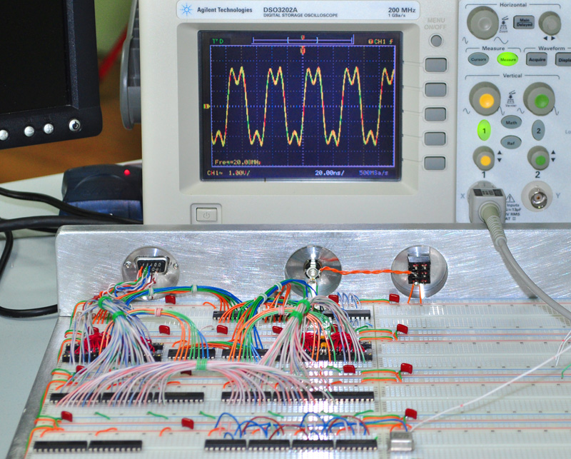
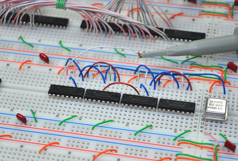
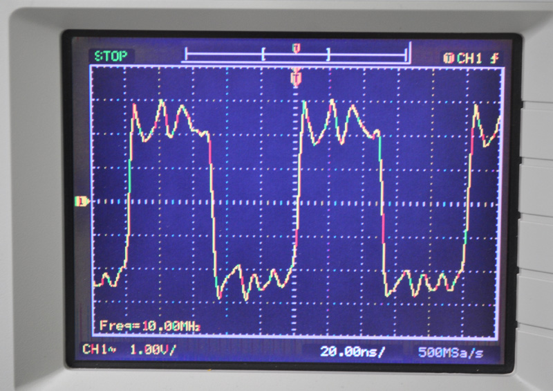
On this one, my max speed is 20MHz through the VGA system and GPU. How I made this work in my current (smaller) breadboard setup is to add clock synced 74HC574 registers after any pathway exceeding 30ns. Much like doing it in HDL, this has worked remarkable well on my breadboard designs.
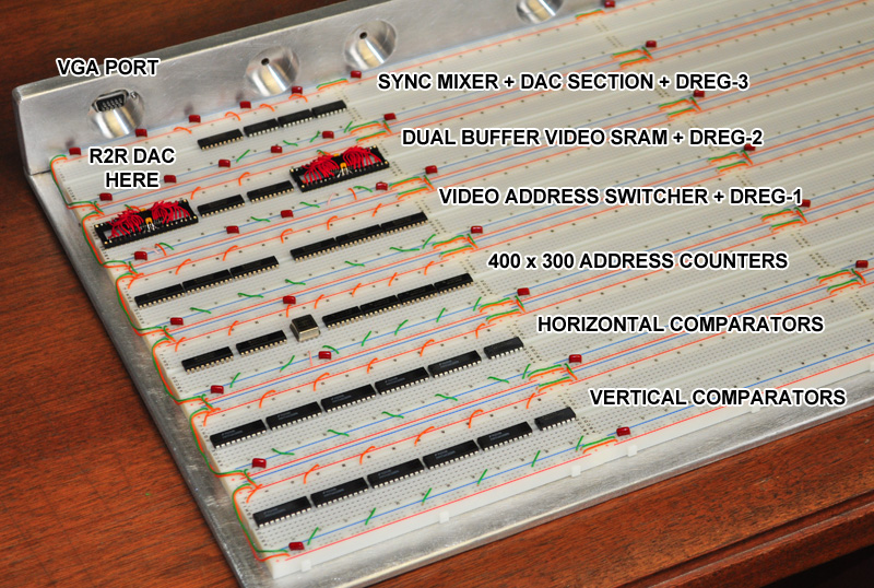
Just from the output of the video buffer SRAM to the R2R DAC for instance, I have 3 registers in the pathway!
This way, I have accounted for not only all of the issues with breading, but also the worst case propagation of all of my components and then some.
It takes only a small level of support logic to deal with delayed clock arrivals.
Hell, my original circuit even used 15ns SRAMS and a 138 decoder, and it was pulling 640x480 at 25.175MHz.
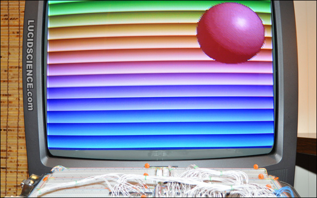
I only lowered the clock to satisfy the 800x600 (divided in half) VGA standard.
So I absolutely and completely agree with everything you said, and have found a way around these issues thanks to many, many late nights of trial, error, smoke, and mirrors.
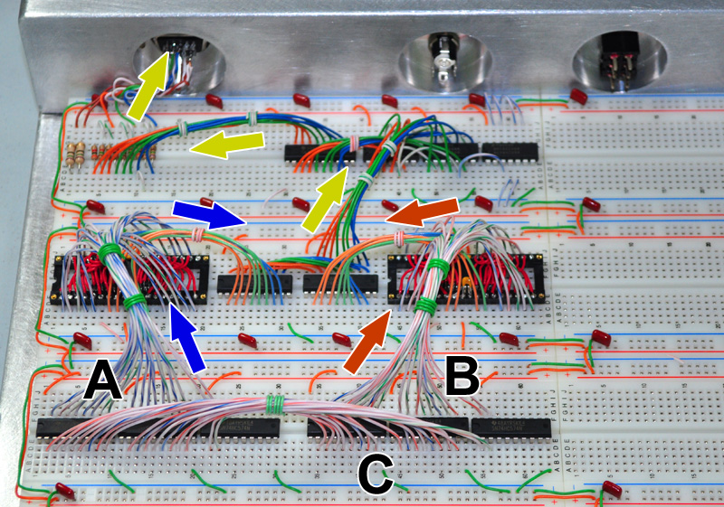
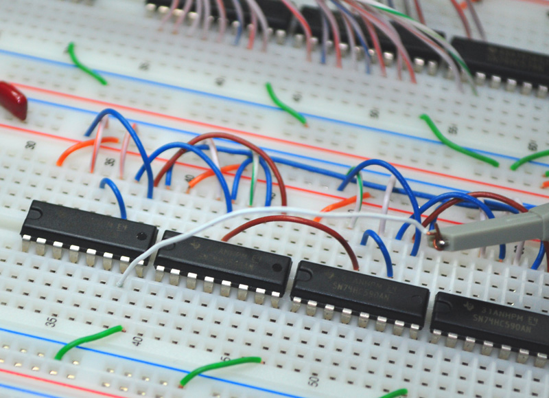
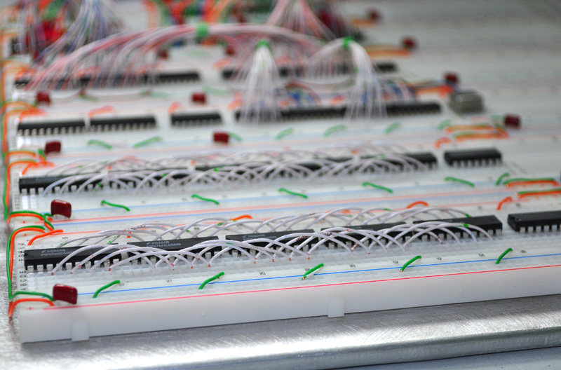
I also lay out my boards in such a segregated way so that no high speed path exceeds 8 inches. Video, GPU, Sound, and Control systems are all self contained, having their own bus systems.
In this system, the 6502 does not have any access to any other bus besides it's own 64K 10ns SRAM, which is preloaded via support logic on power up. Because of the blazing fast design of my GPU, the 6502 need only issue a few bytes in order to toss a dozen or more multi-sized 256 color sprites around the screen at 60 frames per second, complete with alpha (transparent) pixel control. This is why I am doing sneaky illegal op tricks to listen to the 6502.
I have no doubt that I will meet or exceed every single one of my design goals here, and look forward to detailing how I pulled it all off.
As you can probably guess, I love doing things the most difficult way possible, and have no fear of pushing to the absolute edge of limitations (and sanity).
In one FPGA project, I pushed a 10ns SRAM up to the "impossible" speed of 100MHz to get 1024x768 video by having what I call "2 in the barrel", which means that 2 clock pulses are still propagating through a bus before reaching an IO port. Imagine the coding and hardware required for that kind of high speed GPU! Oh the fun of it all.
I enjoyed the sticky thread on high speed design and think it should be required reading just to enter this forum!
The only thing I would add at the end would be...
... but there are ways around every single limitation you have just been taught!
Anyhow, thanks for your logical and sound speed limit advice, I will keep it in mind as I pass the next minivan in a no passing zone, doing 50 over the limit!
Hopefully this weekend will offer a rainy day so I can start putting some black magic into the immortal 6502!!
Cheers,
Radical Brad
GARTHWILSON wrote:
banedon wrote:
I was wondering how you managed to go for 10ns SRAMs as the best I could find is 15ns Cypress CY7C199CN in DIP. I like your solution, although it looks a bit fiddly/time consuming!
Quote:
but my downfall isn't my lack of understanding of ringing, ground bounce, propagation, cross-talk, and capacitance. My downfall has been overwhelming success!!
The Cray-1 ran at 80MHz with long connections, but they were twisted pairs, with each signal wire being twisted with its own ground wire grounded at both ends, so each one was a legitimate transmission line.