6502.org Forum  Projects  Code  Documents  Tools  Forum
It is currently Tue Nov 12, 2024 6:20 pm

All times are UTC


Post new topic Reply to topic  [ 91 posts ]  Go to page Previous  1, 2, 3, 4, 5, 6, 7  Next
Author Message
PostPosted: Thu Nov 06, 2014 1:44 pm 
Offline
User avatar

Joined: Fri Dec 11, 2009 3:50 pm
Posts: 3367
Location: Ontario, Canada
Garth, it sounds as if you're contemplating a new design... generation two of the Workbench Computer, perhaps? Early in this thread you mentioned the products from Data Delay Devices, and those seem intriguing indeed! Their variable delay lines are listed here: http://www.datadelay.com/asp/variable.asp

As these seem small and easy to work with, would you contemplate including a couple of these in your new machine? It seems a small price to pay for both researching the '816 timing envelope and achieving maximal timing for the new computer itself.

( For those new to this thread, maximal '816 timing is non-trivial, with interdependent issues of timing, bus contention, signal quality and power consumption. Also, the '816 datasheet lacks many of the pertinent bus timing specs, as noted in the lead post. )

cheers
Jeff

_________________
In 1988 my 65C02 got six new registers and 44 new full-speed instructions!
https://laughtonelectronics.com/Arcana/ ... mmary.html


Top
 Profile  
Reply with quote  
PostPosted: Thu Nov 06, 2014 6:01 pm 
Offline
User avatar

Joined: Thu May 28, 2009 9:46 pm
Posts: 8482
Location: Midwestern USA
GARTHWILSON wrote:
Daryl, what was the power supply current, and how did the data bus lines and the processor's power supply pins look on a fast 'scope? (You too BDD with the POC.)

Funny you should ask, Garth. :D BCS Technology recently acquired a new higher-end digital camera that takes exceptionally good photos, and has a wide focal range, from less than six inches to upwards of a mile (see attachment for just how close a closeup it can take). It should be able to take sharp pictures of 'scope traces, something that I had considerable trouble doing with my previous camera.

What I'd like to be able to do is figure out how to secure the camera to the bezel of the HP 1725 'scope we have on the electronics bench so photos are taken at close range without surrounding light interference. At one time, camera adapters for that purpose used to be readily available, but I haven't seen anything of the sort in recent years. These adapters held the camera at a precise position, minimizing image distortion caused by the lens not being dead square to the CRT face and eliminating blurriness caused by having shaky hands (that describes me these days :lol:). They also included a hood that completely excluded surrounding light. Way back when in my bench technician days, I used such an arrangement to take Polaroids of 'scope traces for use in technical manuals.

Anyhow, I have been wanting to get a collection of 'scope images of the various signals on POC V1.1 for comparison to POC V2 when it gets built. So I will make the effort to get something as soon as I work out how to set up the camera for the purpose.
Attachment:
File comment: POC Screen Shot from Six Inches
close_up.gif
close_up.gif [ 2.08 MiB | Viewed 3840 times ]

_________________
x86?  We ain't got no x86.  We don't NEED no stinking x86!


Top
 Profile  
Reply with quote  
PostPosted: Thu Nov 06, 2014 7:54 pm 
Offline
User avatar

Joined: Fri Aug 30, 2002 1:09 am
Posts: 8540
Location: Southern California
BDD, what kind of camera? I got my wife a Cannon PowerShot A550 6.5 years ago for about $250, and in the close-up mode, it can read the values printed on 0603 chip resistors just fine. (The values don't get printed on 0402 and smaller.) She seldom uses it, so I use it for the pictures I post. I usually hold it by hand, but once in a while I get a tripod out. Our daughter-in-law's father has a camera that was close to a thousand dollars five years ago and has some sort of image stabilization; so when he took pictures at her graduation last May and at our son's the year before, in spite of how far we were sitting from the platform, he could zoom in and fill the picture with their upper body and still get no shaking in the picture, in spite of holding the camera by hand and the graduations being at dusk. Amazing.

Daryl, 350-400mA seems quite high, but then I was remembering that the CPLD you used for the 65SPI chip ran pretty hot, so I assume that's where a lot of that current is going. My 5MHz 65802 workbench computer plus a smaller, dedicated-purpose 1MHz 65c02 one which I always run at the same time take 140mA combined, and that includes the RS-232 and a mini-tester that's always on the RS-232 port with its LEDs going. The 5V regulators are linear.

Jeff, yes, I keep thinking about the next-generation workbench computer, and I would like to try the DDD adjustable delay lines to get the best performance. As for your musing on page 1,
Quote:
Stated another way, the dead time is zero even before a margin is subtracted for variability in logic and tri-state delays. Of course the variability might trend in your favor, creating a dead time. But it equally might trend the other way and create bus contention. I'm not aware of any really good solution for this

something to this effect might do it, if I didn't get too hurried and mess up (not showing any adjustable delay lines):
Attachment:
816CAS.jpg
816CAS.jpg [ 40.18 KiB | Viewed 3833 times ]

_________________
http://WilsonMinesCo.com/ lots of 6502 resources
The "second front page" is http://wilsonminesco.com/links.html .
What's an additional VIA among friends, anyhow?


Top
 Profile  
Reply with quote  
PostPosted: Fri Nov 07, 2014 12:42 am 
Offline
User avatar

Joined: Fri Dec 11, 2009 3:50 pm
Posts: 3367
Location: Ontario, Canada
Nice, Garth -- I like how the duration of the 245's enable time is curtailed by the NAND pulse-shrinking circuit. That gives a bit of dead time to serve as a timing cushion and prevent bus contention between the 816 and the '245. But, as you know, a too-generous cushion will cause you to fall short of the 816's true performance potential, and that's where the variable delays come in. (I realize your diagram omits the variable delays units.)

If it's to be a quest for absolute max performance, I assume you'll also provide a means to experiment with clock duty cycles other than 50%. It'd be no surprise if actual (rather than documented) minimum pulse-width for Phase2 low differs somewhat from the actual minimum pulse-width for Phase2 high. Only experimentation will reveal this. Perhaps your clock oscillator should be made of two variable-delay units connected nose-to-tail in a loop. :idea: One delay unit would determine the Phase2-high time and the other'd set the Phase2-low time. (You'd need an inverter in the loop, too, but I'm sure you get the idea.)

Also on the absolute max performance checklist, remember to consider a FET bus switch such as 74bct3245 as a drop-in replacement for the '245. That'd be a tradeoff. The device has near-zero prop delay, which gains you some speed, but the gain would be reduced (or in a large system even reversed) by capacitive loading, which a FET bus switch won't buffer.

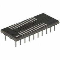
A FET bus switch could also be considered as a faster replacement for the '573 bank-address latch. We discussed this privately -- allowing the RAM address inputs to dynamically hold their state via capacitance. Pinout-wise you'd have to finagle things slightly but the '573 and 'bct3245 are both arranged 8-bits broadside, so it'd be doable -- especially if you're using one of these adapters to place the SOIC bus switch IC on a .1" grid.

-- Jeff
ps to BDD - I think the main obstacles to photographing an oscilloscope screen can be overcome with just some patience, a tripod, and a means to avoid reflections. This means keeping the camera and any other reflected-view objects in the dark or obscured from sight. A hood would do the trick... or we could take a masterful tip from Ford Prefect and use a towel! :)
Attachment:
Aries Electronics 20-350000-10 adapter.jpg
Aries Electronics 20-350000-10 adapter.jpg [ 16.14 KiB | Viewed 3825 times ]

_________________
In 1988 my 65C02 got six new registers and 44 new full-speed instructions!
https://laughtonelectronics.com/Arcana/ ... mmary.html


Top
 Profile  
Reply with quote  
PostPosted: Fri Nov 07, 2014 1:41 am 
Offline
User avatar

Joined: Fri Aug 30, 2002 1:09 am
Posts: 8540
Location: Southern California
Dr Jefyll wrote:
Nice, Garth -- I like how the duration of the 245's enable time is curtailed by the NAND pulse-shrinking circuit. That gives a bit of dead time to serve as a timing cushion and prevent bus contention between the 816 and the '245. But, as you know, a too-generous cushion will cause you to fall short of the 816's true performance potential, and that's where the variable delays come in. (I realize your diagram omits the variable delays units.)

The diagram was just to show the idea. Since there's no minimum prop. delay spec., it would be hard to know what you'll end up with unless you can measure with nanosecond resolution and plug in different ICs until you find the one that gives the delay you want. It will vary some with temperature, but not enough to cause problems in this case.

Quote:
If it's to be a quest for absolute max performance, I assume you'll also provide a means to experiment with clock duty cycles other than 50%. It'd be no surprise if actual (rather than documented) minimum pulse-width for Phase2 low differs somewhat from the actual minimum pulse-width for Phase2 high. Only experimentation will reveal this. Perhaps your clock oscillator should be made of two variable-delay units connected nose-to-tail in a loop. :idea: One delay unit would determine the Phase2-high time and the other'd set the Phase2-low time. (You'd need an inverter in the loop, too, but I'm sure you get the idea.)

You could make the oscillator with just the inverter plus delays, but then you wouldn't have crystal accuracy. I've made VFOs (variable-frequency oscillators) before, to test how fast the thing could go before it starts having problems. What I might do for this one is to use the external VFO to set the frequency, and an onboard delay line to set the phase-2-high time, find the minimum phase-2-high and phase-2-low times, then replace the VFO with a crystal oscillator perhaps 20% lower so there's some known margin for reliability, and stretch the phase-2-high time by the matching amount. One could use use a peltier device to get the processor cold to run faster, but you don't gain enough to make it worth it. I don't particularly want to deal with condensation issues either.

Quote:
Also on the absolute max performance checklist, remember to consider a FET bus switch such as 74bct3245 as a drop-in replacement for the '245. That'd be a tradeoff. The device has near-zero prop delay, which gains you some speed, but the gain would be reduced (or in a large system even reversed) by capacitive loading, which a FET bus switch won't buffer.

A FET bus switch could also be considered as a faster replacement for the '573 bank-address latch. We discussed this privately -- allowing the RAM address inputs to dynamically hold their state via capacitance. Pinout-wise you'd have to finagle things slightly but the '573 and 'bct3245 are both arranged 8-bits broadside, so it'd be doable -- especially if you're using one of these adapters to place the SOIC bus switch IC on a .1" grid.

I do have a bunch of those in different sizes, since there are so many parts now that aren't available in DIP. Sometimes a twenty-cent part suddenly becomes a six-dollar part; but it's ok since you're not using it for production (otherwise you'd lay out an SMT PCB). I definitely like the idea of the transparent FET switch for certain things. You don't even need a direction pin.

_________________
http://WilsonMinesCo.com/ lots of 6502 resources
The "second front page" is http://wilsonminesco.com/links.html .
What's an additional VIA among friends, anyhow?


Top
 Profile  
Reply with quote  
PostPosted: Tue Jan 06, 2015 6:23 pm 
Offline

Joined: Mon Jan 07, 2013 2:42 pm
Posts: 576
Location: Just outside Berlin, Germany
I have a potentially very stupid question about the Bank Address Latching Circuit on the first page (the one from the 65816 data sheet): Why is there a diamond in the middle of the BA/D data bus (second line from the bottom)? I know that symbol as "Controlled Voltage Source" (see http://www.rapidtables.com/electric/ele ... ymbols.htm) which really doesn't make sense.


Top
 Profile  
Reply with quote  
PostPosted: Tue Jan 06, 2015 6:48 pm 
Offline
User avatar

Joined: Thu Dec 11, 2008 1:28 pm
Posts: 10977
Location: England
Best guess: it was an attempt to indicate that the bus is bidirectional at that point. I didn't really notice it, but I don't recognise it as a convention.


Top
 Profile  
Reply with quote  
PostPosted: Fri Jan 30, 2015 9:44 pm 
Offline

Joined: Wed Feb 05, 2014 7:02 pm
Posts: 158
BigDumbDinosaur wrote:
Arlet wrote:
However, looking at the behaviour of the '816, I can't understand why they changed the perfectly fine 'C02 workarounds, and changed it back into bad address cycles, but protected by VDA/VPA, basically requiring the hardware designer to take into account those two additional signals in hardware addressing.

Actually, there's a perverse logic to the presence of VDA and VPA. Collectively, these signals tell the circuit logic when the address bus is valid. Individually, they tell the circuit what it is the MPU is doing. One could easily implement a von Neumann or a Harvard architecture merely by correct usage of these signals. Another possibility is cycle-steal DMA by doing a DMA op when both VDA and VPA are false.
Someone on this forum who started another thread on the '816 considers this a hardware bug, though I'm not sure I agree. Arlet's point: Does the '816 predate the 'C02? Something I've noticed about the datasheet though. Page 52, Section 7.5 states that invalid addresses are only generated during a specific low-byte index-addressing internal addition that is propagated to the external buses. Based on the following snippet:

WDC65816 Datasheet wrote:
The Page and Bank addresses could also be invalid.
BA0-7 and A8-15 are invalid. According to footnote (4) of Table 5.7, invalid addresses are only generated in Emulation mode or when X=1 in Native mode (8-bit index), and ONLY during a write or page boundary crossing (presumably the extra cycle to fix the NMOS 6502 page boundary bug). I interpret this as: if X=0 and is left alone after native mode init, VDA/VPA need not qualify a memory access, resulting in less propogation delay for a discrete design.


BigDumbDinosaur wrote:
EDIT: Cogitation leads me to believe that cycle steal DMA is a pipe dream. There are too few instructions with dead cycles, especially instructions that are most commonly used.
I hope that's wrong, tbh. For a DMA controller, cycle-steal or transparent DMA honestly would be easy to implement (note to self- don't use Verilog) thanks to those control signals.

On an unrelated note: Footnote (1) of Table 7.5 says to add one cycle if EITHER M or X=0. Many of these instructions, however, show the extra cycle being added only due to 16-bit accumulator (M=0) and not due to 16-bit index. Has anyone tested whether the extra cycle for such instructions is added when M=1 and X=0? Indeed, there are instructions where having X=0 vs X=1 matters- Footnote (4). I guess the logic is the the '816 actually loads all 16-bits of the accumulator during reads, even when A is 8-bit. But this doesn't explain an extra cycle for writes when M=1 and X=0?


Top
 Profile  
Reply with quote  
PostPosted: Fri Jan 30, 2015 10:00 pm 
Offline
User avatar

Joined: Thu Dec 11, 2008 1:28 pm
Posts: 10977
Location: England
If the 816 reintroduces some inconveniences of the NMOS 6502 which the C02 fixed, might that be because Apple and Mensch were working together to make a highly compatible micro, for use in what became the IIgs? Mensch said: "In the case of an Apple computer, as an example, the way that [Apple co-founder Steve] Wozniak did his disk controller, we had to make modifications because of the way that the disk controller works."

Cheers
Ed


Top
 Profile  
Reply with quote  
PostPosted: Sat Jan 31, 2015 2:39 am 
Offline
User avatar

Joined: Thu May 28, 2009 9:46 pm
Posts: 8482
Location: Midwestern USA
cr1901 wrote:
Someone on this forum who started another thread on the '816 considers this a hardware bug, though I'm not sure I agree. Arlet's point: Does the '816 predate the 'C02? Something I've noticed about the datasheet though. Page 52, Section 7.5 states that invalid addresses are only generated during a specific low-byte index-addressing internal addition that is propagated to the external buses. Based on the following snippet:

WDC65816 Datasheet wrote:
The Page and Bank addresses could also be invalid.
BA0-7 and A8-15 are invalid. According to footnote (4) of Table 5.7, invalid addresses are only generated in Emulation mode or when X=1 in Native mode (8-bit index), and ONLY during a write or page boundary crossing (presumably the extra cycle to fix the NMOS 6502 page boundary bug). I interpret this as: if X=0 and is left alone after native mode init, VDA/VPA need not qualify a memory access, resulting in less propogation delay for a discrete design...

The data sheet's wording often seems to be contradictory in trying to explain when invalid addresses are generated. The best thing to do is consult the operations table starting on page 38 of the data sheet.

_________________
x86?  We ain't got no x86.  We don't NEED no stinking x86!


Top
 Profile  
Reply with quote  
PostPosted: Wed Apr 22, 2020 7:24 am 
Offline
User avatar

Joined: Wed Apr 22, 2020 7:17 am
Posts: 6
Location: Madrid, Spain
I am quite late to the party. But I have a question.

Yes, it is clear that even using a transceiver in the data bus there could be contention. But, we have some ways to inhibit 65816 driving the bus, right? Would it be possible to use the
BE (Bus Enable) signal to prevent it to drive the data bus with bank address once it has been successfully latched? Thanks to that, you have some grade of control to avoid contention between bank address and memory reads.

Is that wrong?

Edit: I initially said RDY signal, but I meant BE.


Last edited by apoloval on Wed Apr 22, 2020 12:02 pm, edited 2 times in total.

Top
 Profile  
Reply with quote  
PostPosted: Wed Apr 22, 2020 8:12 am 
Offline
User avatar

Joined: Thu Dec 11, 2008 1:28 pm
Posts: 10977
Location: England
Just for reference, from 2015:
cr1901 wrote:
The 65816 does NOT drive the bank address while RDY is low.
...
    If RDY is driven low during PHI2 high, the '816 will NOT drive a bank address onto the bus during the next PHI2 low.

    If RDY is driven low during PHI2 low, a read during PHI2 high will occur as normal, and during the same situation as above applies. Have not tested writes yet.

    If RDY is driven high during PHI2 high, the '816 WILL drive a new address onto the bank bus during the next cycle. Obviously, the I/O device better in fact be ready, and have some breathing room to satisfy setup time. Otherwise it is probably best to drive RDY high while PHI2 is low.

    If RDY is driven high during PHI2 low, a read during PHI2 high will occur as normal, and the '816 WILL drive a new address onto the bank bus during the next cycle.


My feeling is that this is saying that RDY is a synchronous input sampled on the usual falling edge of the clock and affects the subsequent phase: it's not the Bus Enable input BE (which I'm guessing is async... but really ought to check!)


Top
 Profile  
Reply with quote  
PostPosted: Wed Apr 22, 2020 9:15 am 
Offline

Joined: Mon May 21, 2018 8:09 pm
Posts: 1462
AFAIK, BE is asynchronous and simply tri-states the appropriate pins.

I think of RDY as simply controlling whether the next Phi2 falling edge is effective on the CPU. If RDY is low, then Phi2 is internally held high, and this is externally visible on the '816 due to the bank address multiplexing.

In order to halt the CPU for a DMA access, it's necessary to use both BE and RDY. RDY to halt the CPU (so it doesn't crash due to bogus data on the bus), and BE to allow the DMA master to drive the address lines.


Top
 Profile  
Reply with quote  
PostPosted: Wed Apr 22, 2020 12:21 pm 
Offline
User avatar

Joined: Wed Apr 22, 2020 7:17 am
Posts: 6
Location: Madrid, Spain
Yep, my fault. I said RDY, but I meant BE (Bus Enable).

BE does not interrupt the CPU at all. It just makes the CPU to stop driving the address and data buffers. Once the memory controller latches the bank address after PHI2 rise, it could also deactivate BE. And hence ensure the data bus will be free for the memory to write the read result. It can activate BE back again a while before PHI2 fall edge. Which is the instant when the CPU will read the data bus.

Something like this might require 3 different clock signals at the same frecuency but shifted a little bit in time. Let's call them A, B and C. Using a shift of 10ns would be okay according to the timing diagrams. This is something that could be obtained with a 74HC04 part. B could be the clock input for the CPU. C is 10ns ahead in time, and A is 10ns delayed.

On the rise edge of B, the bank address is latched. On the rise edge of A, the BE signal is deactivated, the memory request signal (some sort of Memory Address Strobe) is also activated. This means the CPU stops driving the data bus 10ns after PHI2 rise. And memory chips are still not selected. Thus, there is no bus contention there. On the fall edge of C, BE is enabled again. This is 10ns before fall edge of PHI2. And the memory IC must have written the data at this point in time (memory access time must be below 15ns).

For the hold times, something similar can be done. On A fall edge, the memory OE signal is deactivated. This is 10ns after PHI2 fall edge. So the hold time of the read byte is ensured.

Does it make any sense?


Top
 Profile  
Reply with quote  
PostPosted: Wed Apr 22, 2020 12:43 pm 
Offline

Joined: Mon May 21, 2018 8:09 pm
Posts: 1462
I might be missing the point of what you're trying to achieve here. It sounds overly complicated compared to using an external tristate buffer and doing DMA during Phi1.


Top
 Profile  
Reply with quote  
Display posts from previous:  Sort by  
Post new topic Reply to topic  [ 91 posts ]  Go to page Previous  1, 2, 3, 4, 5, 6, 7  Next

All times are UTC


Who is online

Users browsing this forum: Google [Bot] and 4 guests


You cannot post new topics in this forum
You cannot reply to topics in this forum
You cannot edit your posts in this forum
You cannot delete your posts in this forum
You cannot post attachments in this forum

Search for:
Jump to: