6502.org Forum  Projects  Code  Documents  Tools  Forum
It is currently Wed Sep 25, 2024 2:35 am

All times are UTC


Post new topic Reply to topic  [ 12 posts ] 
Author Message
PostPosted: Wed Jan 30, 2013 8:42 pm 
Offline

Joined: Mon Jan 28, 2013 3:09 am
Posts: 35
In the following schematic there are two 90° degrees crossings marked with a red circle:

Image

In both cases are the lines electrically connected or do they just cross over without making contact?

Btw, should I rather post this in the hardware subforum?


Top
 Profile  
Reply with quote  
PostPosted: Wed Jan 30, 2013 9:12 pm 
Offline
User avatar

Joined: Thu Dec 11, 2008 1:28 pm
Posts: 10938
Location: England
There is a connection in both cases: that's the only intepretation which makes sense. Does Balazs generally use solid dots to indicate a connection, or does he generally use little jumps to indicate no connection? Those two conventions are reasonably standard. It's also possible that it's a mistake not to have drawn connection dots.

Cheers
Ed


Top
 Profile  
Reply with quote  
PostPosted: Wed Jan 30, 2013 10:54 pm 
Offline

Joined: Mon Jan 28, 2013 3:09 am
Posts: 35
He uses jumps to indicate no connection. So I will assume no jump implies a connection from now on.


Top
 Profile  
Reply with quote  
PostPosted: Thu Jan 31, 2013 3:43 am 
Offline
User avatar

Joined: Thu Dec 11, 2008 1:28 pm
Posts: 10938
Location: England
Do beware that there are few cases where the visual6502 netlist differs from Balazs' schematic: as the visual6502 simulates correctly and the team were working from better photos of a deprocessed chip, we should assume that visual6502 is correct.
It's still an extremely useful (and impressive!) piece of work.
Cheers
Ed


Top
 Profile  
Reply with quote  
PostPosted: Thu Jan 31, 2013 5:12 am 
Offline
User avatar

Joined: Thu May 28, 2009 9:46 pm
Posts: 8395
Location: Midwestern USA
Most of the electrical drafting programs I've used over the years indicate a connection with a dot at the point of intersection. The jump-over seemed to be more common back when most schematics were hand-drawn. I still use it in my sketches, mostly as force of habit.

_________________
x86?  We ain't got no x86.  We don't NEED no stinking x86!


Top
 Profile  
Reply with quote  
PostPosted: Thu Jan 31, 2013 6:31 am 
Offline
User avatar

Joined: Tue Nov 16, 2010 8:00 am
Posts: 2353
Location: Gouda, The Netherlands
I've also seen the convention where a T-junction always means a connection, and a 4-way intersection means no connection.


Top
 Profile  
Reply with quote  
PostPosted: Thu Jan 31, 2013 5:32 pm 
Offline

Joined: Mon Jan 28, 2013 3:09 am
Posts: 35
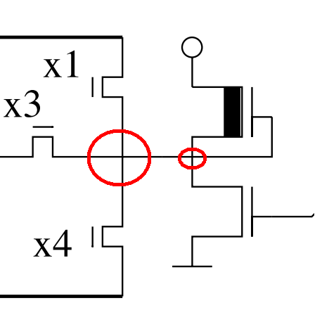
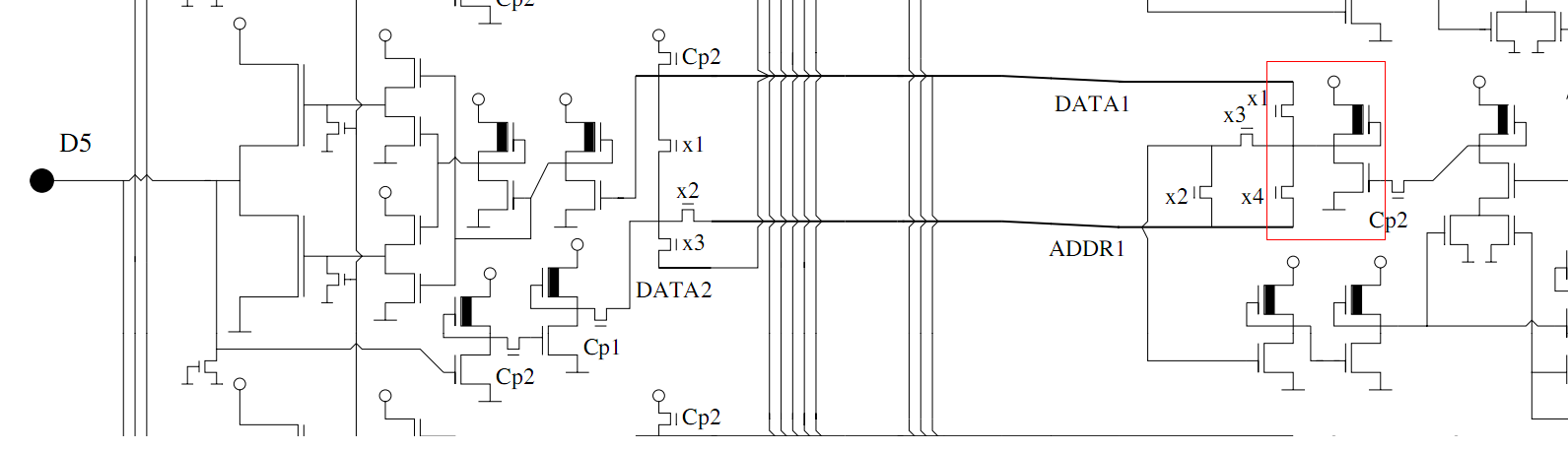
Let me give a bit more context to the image. The red rectangle marks the area where the smaller pic is taken from. It is from the top left part of the 6502 schematic where the data bus is read in(this corresponds to the bottom right part of the visual6502 simulation because the schematic is rotated 180° in relation to the simulation). The same circuit is repeated for every bit D0-D7:

Image

The complete schematic can be obtained here:
http://www.downloads.reactivemicro.com/Public/Electronics/CPU/


Top
 Profile  
Reply with quote  
PostPosted: Thu Jan 31, 2013 5:42 pm 
Offline

Joined: Mon Jan 28, 2013 3:09 am
Posts: 35
BigEd wrote:
Do beware that there are few cases where the visual6502 netlist differs from Balazs' schematic: as the visual6502 simulates correctly and the team were working from better photos of a deprocessed chip, we should assume that visual6502 is correct.


Yes Ed, I'm using the visual simulator as my primary source and use the schematic only as a guideline/help to understand the simulation.


Top
 Profile  
Reply with quote  
PostPosted: Fri Feb 01, 2013 5:40 am 
Offline
User avatar

Joined: Fri Aug 30, 2002 1:09 am
Posts: 8517
Location: Southern California
Quote:
Btw, should I rather post this in the hardware subforum?

This one is ok. Since there are so many regarding the visual6502 though (there's nothing wrong with that-- keep it up!), I edited the titles to start with "visual6502:" to make it easier to sort things mentally as one looks down the list of titles.

_________________
http://WilsonMinesCo.com/ lots of 6502 resources
The "second front page" is http://wilsonminesco.com/links.html .
What's an additional VIA among friends, anyhow?


Top
 Profile  
Reply with quote  
PostPosted: Fri Feb 01, 2013 9:21 am 
Offline
User avatar

Joined: Thu Dec 11, 2008 1:28 pm
Posts: 10938
Location: England
Hmm, I'd say these questions are more about the (NMOS) 6502 implementation - visual6502 is just a means to an end. Balazs' schematics and Hanson's block diagram are other sources (as indeed are the original schematics, both Atari's and MOS', for those who have access to them.)

But I'm all in favour of clarity in thread titles.

Cheers
Ed


Top
 Profile  
Reply with quote  
PostPosted: Wed Feb 06, 2013 7:47 pm 
Offline

Joined: Mon Jan 28, 2013 3:09 am
Posts: 35
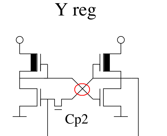
The following is a storage unit from Balasz diagram and the intersecting wires in the red oval do not touch each other(confirmed by visual6502). So the diagram is not totally consistent or maybe it uses the convention that a 4-way intersection means no connection.

Image

Corresponding storage unit in visual6502:

http://www.visual6502.org/JSSim/expert.html?nosim=t&panx=133.3&pany=515.3&zoom=12.8


Top
 Profile  
Reply with quote  
PostPosted: Wed Feb 06, 2013 7:50 pm 
Offline
User avatar

Joined: Thu Dec 11, 2008 1:28 pm
Posts: 10938
Location: England
Mmm, not totally consistent is the best hypothesis.


Top
 Profile  
Reply with quote  
Display posts from previous:  Sort by  
Post new topic Reply to topic  [ 12 posts ] 

All times are UTC


Who is online

Users browsing this forum: No registered users and 11 guests


You cannot post new topics in this forum
You cannot reply to topics in this forum
You cannot edit your posts in this forum
You cannot delete your posts in this forum
You cannot post attachments in this forum

Search for:
Jump to: