6502.org Forum  Projects  Code  Documents  Tools  Forum
It is currently Sat Nov 23, 2024 9:59 am

All times are UTC


Forum locked This topic is locked, you cannot edit posts or make further replies.  [ 55 posts ]  Go to page Previous  1, 2, 3, 4  Next
Author Message
 Post subject: [85.16] Tip of the day
PostPosted: Sat Dec 30, 2000 6:57 am 
Offline
User avatar

Joined: Fri Aug 30, 2002 1:09 am
Posts: 8545
Location: Southern California
Tip of the day, #15

For a fast 8-bit D/A output using a 6522 port (or any parallel output port), connect an inexpensive DAC0808.  To output a new analog level, all you have to do is write the new number to the port.  That's it—no clocking, strobing, shifting, etc..  When you're not using the D/A convertor, its presence can be ignored and the port can be used as if the D/A were not even there.  This D/A has a current output, so you'll need an op amp if you want to convert to voltage.  I have used this D/A as a digital gain control too, superimposing the AC input signal onto the voltage reference.  With data convertors, make sure you reference the analog signals to the ground pin of the convertor, and not to ground elsewhere in the computer where digital noise would be a problem.  I bring these grounds out to pins on the I/O connector, then put large ferrite beads over pairs of wires of ground and analog connections.  For more details, E-mail me directly at wilsonmineszdslextremezcom (replacing the z's with @ and .).  I don't mind.  Really.

Edit: Circuit with notes at http://wilsonminesco.com/6502primer/potpourri.html#DAC

_________________
http://WilsonMinesCo.com/ lots of 6502 resources
The "second front page" is http://wilsonminesco.com/links.html .
What's an additional VIA among friends, anyhow?


Last edited by GARTHWILSON on Wed Feb 22, 2012 8:43 am, edited 2 times in total.

Report this post
Top
 Profile  
Reply with quote  
 Post subject: [85.17] Tip of the day
PostPosted: Sun Dec 31, 2000 5:39 am 
Offline
User avatar

Joined: Fri Aug 30, 2002 1:09 am
Posts: 8545
Location: Southern California
Tip of the day, #16

For a fast 8-bit A/D, connect an ADC0820 to PA or PB of a 6522, 6526, etc..  Ground the A/D's mode pin.  Select the A/D with one other I/O bit from the 65xx to both the RD\ and CS\ of the A/D.  By the time a 1MHz or 2MHz 6502 gets to the next machine-language instruction to read the port, the A/D will already have the data ready.  Read it, then de-select the A/D by setting the RD\-CS\ bit high again.  (If you're running a 6502 at 200kHz or less, you can put the ADC0820 on the data bus and just read it like a memory location.)  No clocking, interrupts, etc. are needed.  It has its own track and hold too.  The Maxim MAX153 is almost identical but more than twice as fast; but it still needs a NOP before the read on my 5MHz 65c02 workbench computer to ensure dependable output.  I've used it for things like a make-shift digital 'scope, monitoring voltages and temperatures, and recording short audio snips.  8-bit audio gives a dynamic range similar to that of cassettes, but with potentially much better frequency response and distortion figures.  (Speech is intelligible with 2-bit sampling if the dynamic range is highly compressed.)  E-mail me directly for a few simple circuit considerations to consistently get accurate results.

Edit: circuit, with notes and driver code, at http://wilsonminesco.com/6502primer/potpourri.html#ADC

_________________
http://WilsonMinesCo.com/ lots of 6502 resources
The "second front page" is http://wilsonminesco.com/links.html .
What's an additional VIA among friends, anyhow?


Last edited by GARTHWILSON on Wed Feb 22, 2012 8:42 am, edited 1 time in total.

Report this post
Top
 Profile  
Reply with quote  
 Post subject: [85.18] Tip of the day
PostPosted: Mon Jan 01, 2001 5:58 am 
Offline
User avatar

Joined: Fri Aug 30, 2002 1:09 am
Posts: 8545
Location: Southern California
Tip of the day, #17

You can use the 6522's PB7 and free-running T1 to output a beep signal, or clock out an exact number of cycles from an arbitrary waveform generator, while leaving the µP free to do other things at the same time.  You'll need the 2 msb's of the 6522's ACR to be 11.  You might use a timer interrupt to turn off the beep, or a cycle-counting interrupt to stop the arb at the right time.  Happy New Year.

_________________
http://WilsonMinesCo.com/ lots of 6502 resources
The "second front page" is http://wilsonminesco.com/links.html .
What's an additional VIA among friends, anyhow?


Report this post
Top
 Profile  
Reply with quote  
 Post subject: [85.19] Tip of the day
PostPosted: Tue Jan 02, 2001 3:52 am 
Offline
User avatar

Joined: Fri Aug 30, 2002 1:09 am
Posts: 8545
Location: Southern California
Tip of the day, #18

Use a 6522's T1 for a time reference, and T2 to count external pulses on PB6 to make a frequency counter.  The 6522's ACR<5> will need to be a 1.  Instead of using T2's interrupt-on-rollover feature, just read the T2 counter, then read it again after a certain amount of time to see how many pulses were counted in that amount of time.  You might want to have T1's rollover cause an interrupt, read T2, and then read it again at the next T1 interrupt.  For period, it might be easier to have T2 interrupt, and then read T1's counter at the interrupt.

_________________
http://WilsonMinesCo.com/ lots of 6502 resources
The "second front page" is http://wilsonminesco.com/links.html .
What's an additional VIA among friends, anyhow?


Last edited by GARTHWILSON on Wed Feb 22, 2012 8:41 am, edited 1 time in total.

Report this post
Top
 Profile  
Reply with quote  
 Post subject: [85.20] Tip of the day
PostPosted: Wed Jan 03, 2001 5:17 am 
Offline
User avatar

Joined: Fri Aug 30, 2002 1:09 am
Posts: 8545
Location: Southern California
Tip of the day, #19

Do a make-shift watchdog timer for an embedded system with one of the timer/counters in a 6522.  Set it up to interrupt when it rolls over, and have your main program loop keep resetting the counter so it never rolls over as long as things are under control.  If the computer crashes with interrupts disabled, this watchdog scheme won't help unless the 6522's interrupt pin is connected to the 6502's NMI\, and it won't work if a wayward routine fowls up the 6522's setup.  (Maybe the part of the main loop that resets the counter should also re-check the set-up.)  So although it's not 100% fool-proof, it may be close enough.

_________________
http://WilsonMinesCo.com/ lots of 6502 resources
The "second front page" is http://wilsonminesco.com/links.html .
What's an additional VIA among friends, anyhow?


Last edited by GARTHWILSON on Wed Feb 22, 2012 8:43 am, edited 2 times in total.

Report this post
Top
 Profile  
Reply with quote  
 Post subject: [85.21] Tip of the day
PostPosted: Thu Jan 04, 2001 4:12 am 
Offline
User avatar

Joined: Fri Aug 30, 2002 1:09 am
Posts: 8545
Location: Southern California
Tip of the day, #20

I stumbled on a difference between the CMD and the Rockwell 65c22's.  The first time I used the 65c22 serial ports to pass data from one 65c02 computer to another, I used CMD's.  When I replaced it with a Rockwell, the program no longer worked.  It wouldn't get started with the first byte.  The reason was that I was checking IFR<2> to see if the SR was ready for another byte.  With CMD, this bit means "SR empty", whereas with the Rockwell, it means "8 shifts completed".  These normally mean the same thing, but my program wouldn't start with the Rockwell part because even though the SR was ready, no shifts had occurred yet because I hadn't given it anything to transmit yet.  I ended up using a RAM byte variable as a flag to tell the loop if the first byte had been sent yet.

_________________
http://WilsonMinesCo.com/ lots of 6502 resources
The "second front page" is http://wilsonminesco.com/links.html .
What's an additional VIA among friends, anyhow?


Last edited by GARTHWILSON on Wed Feb 22, 2012 8:44 am, edited 1 time in total.

Report this post
Top
 Profile  
Reply with quote  
 Post subject: [85.22] Tip of the day
PostPosted: Fri Jan 05, 2001 4:34 am 
Offline
User avatar

Joined: Fri Aug 30, 2002 1:09 am
Posts: 8545
Location: Southern California
Tip of the day, #21

Use the 6502's NMI\ and a 6522's free-running T1 generating interrupts for a real-time clock (RTC).  Even if you don't need time and date, you can use it to time the key de-bouncing and auto repeat, time-out on hardware error (like printer not ready), etc., without using delay loops that keep the computer from doing other things while waiting.  I'm using an NMI every 10ms to update the RTC variables.  It slows the whole system down by about 1%, including looking to see if an alarm is due.  An alarm would tell the computer it's time to do a particular job.  The RTC can of course be stopped if it would cause too much jitter in another job being done in the foreground.

There is same code just over halfway down the long page of my interrupts primer.

We're often told to reserve the NMI for something drastic like power going down; but in most systems the people on this forum are making, what happens in the last milliseconds before power is gone is of no concern.  If you have a system that remembers things when it's off, it probably has batteries and can turn itself off in an orderly fashion.  There's no time to store anything useful on a disc.  If the 6522 used for the RTC goes on the 6502's NMI\, polling for interrupt sources on IRQ\ is simplified, and the RTC never misses a beat when other interrupts hit or are masked.

_________________
http://WilsonMinesCo.com/ lots of 6502 resources
The "second front page" is http://wilsonminesco.com/links.html .
What's an additional VIA among friends, anyhow?


Last edited by GARTHWILSON on Wed Feb 22, 2012 8:45 am, edited 1 time in total.

Report this post
Top
 Profile  
Reply with quote  
 Post subject: [85.23] Tip of the day
PostPosted: Sat Jan 06, 2001 4:15 am 
Offline
User avatar

Joined: Fri Aug 30, 2002 1:09 am
Posts: 8545
Location: Southern California
Tip of the day, #22

RAM needs Φ2 brought into the chip-select logic to avoid invalid writes.  Neither Φ2 nor R/W need to be brought into the chip-select logic for ROM in a 6502 system, but a 65816 system may not latch the correct bank number if ROM output is not disabled when Φ2 is low.  Φ2 must not be brought into the chip-select logic for I/O ICs that have their own Φ2 input, like the 6522 and 6551.

If your RAM were slow enough to need more time (which is unlikely, since SRAM comes in faster speeds than anything else you'll put on your board), you can apply the Φ2 signal to the WE\ and OE\ signals instead.  This will prevent writes to unintended addresses, and prevent possible bus contention, yet still give the RAM more time to respond to its CS\ input if needed.

_________________
http://WilsonMinesCo.com/ lots of 6502 resources
The "second front page" is http://wilsonminesco.com/links.html .
What's an additional VIA among friends, anyhow?


Last edited by GARTHWILSON on Wed Feb 22, 2012 8:46 am, edited 1 time in total.

Report this post
Top
 Profile  
Reply with quote  
 Post subject: [85.24] Tip of the day
PostPosted: Mon Jan 08, 2001 5:32 am 
Offline
User avatar

Joined: Fri Aug 30, 2002 1:09 am
Posts: 8545
Location: Southern California
Tip of the day, #23

You can get RAM, ROM, and plenty of 65xx I/O in your 6502 sytem using a single quad 2-input NAND gate 14-pin IC. Here's one way to do it:

Use one NAND to invert A15, the high address bit, to get A15\. Connect A15\ to the CS\ and OE\ of a 27c256 32Kx8 EPROM, giving you ROM from 8000 to FFFF.

Connect A14 to a 62256 32Kx8 SRAM's A14 and OE\ inputs, and use another NAND for the RAM's CS\ input such that

CS\ = NOT(phase_2 AND A15\). This way you use half the 32Kx8 RAM (16KB), from 0000 to 3FFF.

Connect a third NAND's inputs to A14 and A15\ (derived above), and its output to the CS\ inputs of up to ten I/O ICs like the 6522 and 6551 in the 4000-7FFF range. Individual CS inputs of the various ICs can then go to individual address lines A4,A5,...A13. (The 6522's need A0 to A3 for register selects.)

This scheme is more-or-less what I have on my workbench computer with 3 65c22's and 3 65c51's. Four more could be accomodated without any more glue logic. A tradeoff for the simplicity is that some address ranges in the 16K I/O area duplicate others and thus are essentially unusable; but it fits the purpose nicely.

Image

For more simple address-decoding schemes, see the address-decode section of my 6502 primer. (Actually, you will find the above to be more clear there too.) There is also a basic 6502 computer schematic showing the simple address decoding at http://wilsonminesco.com/6502primer/pot ... ml#BAS_CPU .

_________________
http://WilsonMinesCo.com/ lots of 6502 resources
The "second front page" is http://wilsonminesco.com/links.html .
What's an additional VIA among friends, anyhow?


Report this post
Top
 Profile  
Reply with quote  
 Post subject: [85.25] Tip of the day
PostPosted: Tue Jan 09, 2001 4:22 am 
Offline
User avatar

Joined: Fri Aug 30, 2002 1:09 am
Posts: 8545
Location: Southern California
Tip of the day, #24

An asymmetrical clock may keep your 6502 system from running as fast as it otherwise could. Connecting a crystal or RC directly to the pins of most 65c02's works for non-critical applications; but to improve the timing margins for higher speeds, use an external clock oscillator running at twice the final speed, and use one flip-flop in a 74HC74 or 74AC74 to divide the frequency by two, making the waveform symmetrical in the process. Connect the Q\ output back to the D input, and the oscillator to the flip-flop's clock input. The flip-flop's Q output becomes your new clock source. Here's the connection:

Image

There's more about clock generation in the chapter by that name in the 6502 primer, at http://wilsonminesco.com/6502primer/ClkGen.html .

_________________
http://WilsonMinesCo.com/ lots of 6502 resources
The "second front page" is http://wilsonminesco.com/links.html .
What's an additional VIA among friends, anyhow?


Report this post
Top
 Profile  
Reply with quote  
 Post subject: [85.26] Tip of the day
PostPosted: Wed Jan 10, 2001 4:01 am 
Offline
User avatar

Joined: Fri Aug 30, 2002 1:09 am
Posts: 8545
Location: Southern California
Tip of the day, #25

For easy, compact mass storage, use flash memory with a single power supply voltage and a serial interface. Two large ones I know of are the Atmel AT45D161 2Mx8 (which I've used, and was about $15 in Dec '00), and the AT45DB642 8Mx8 (about $40 in Dec '00). 8Mx8 is about as much as 50 Commodore 64 discs held. This one uses a supply voltage of 2.7 to 3.6 volts; but if you run it on a standard 3.3V, it will be fully compatible with your 5V 6502 system without any level-translation parts because it can tolerate 6V input signals and can output at least 3.1V with a 3.3V supply. These serial flash memories only need four wires for interfacing: clock, serial in, serial out, and chip select. Each additional flash adds one more wire for chip select. There is a write-protect pin for the lowest 128K so you can for example, keep your operating system there so you won't accidentally overwrite it.

Edit, 16 years later: I'm now using the much cheaper 25VF032 4Mx8 SPI flash memory in a tiny SO-8, mounted to tiny PCBs I had made with the SPI-10 interface and am offering for hobbyists. See the front page of my website. There are several other pin-compatible SPI flash ICs that also work on the same tiny board, shown here compared to SD Card and CF card for relative size:

Image

_________________
http://WilsonMinesCo.com/ lots of 6502 resources
The "second front page" is http://wilsonminesco.com/links.html .
What's an additional VIA among friends, anyhow?


Report this post
Top
 Profile  
Reply with quote  
 Post subject: [85.27] Tip of the day
PostPosted: Thu Jan 11, 2001 6:02 am 
Offline
User avatar

Joined: Fri Aug 30, 2002 1:09 am
Posts: 8545
Location: Southern California
Tip of the day, #26

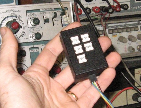
If your small computer project needs a keypad, 3 to 5 keys is often enough. I have Up, Down, Yes/Enter/Select/Continue, No/Cancel/Escape/Exit, and Help/Menu/Edit/Special. In the source code, they're called UPKEY, DNKEY, YESKEY, NOKEY, and HLPKEY. Multi-key combinations (as with "shift") would enhance the possibilities. For my workbench computer, text (mostly source code) is entered by RS-232 from the PC; but the keypad allows quick choices while a program is running.

My workbench computer has these buttons on the board itself, but as I gave it commands from the PC on the desk opposite the workbench and turn around toward the workbench to see instant results, there were times that I wanted the keys within reach without having to get up each time; so I also made a remote keypad and added a pin header on the workbench computer to connect it with a long cord, like this:
Image

A small, portable system we did in the late 80's actually used two keys plus a 2-bit gray-code rotary switch to select menu options and even enter text. For text, rotating the knob would run through a list of characters at the cursor position, and the Enter key selected the current character. It was the Dymo label-maker idea, but special-function characters offered insert & delete, backspace, and so on. Pressing Enter and Exit simultaneously was the equivalent of a "help" key. Text entry was kind of slow, but easy for the user to learn. A later product revision used the above 5-key system instead.

_________________
http://WilsonMinesCo.com/ lots of 6502 resources
The "second front page" is http://wilsonminesco.com/links.html .
What's an additional VIA among friends, anyhow?


Last edited by GARTHWILSON on Sat Mar 03, 2012 8:41 am, edited 2 times in total.

Report this post
Top
 Profile  
Reply with quote  
 Post subject: [85.28] Tip of the day
PostPosted: Fri Jan 12, 2001 5:11 am 
Offline
User avatar

Joined: Fri Aug 30, 2002 1:09 am
Posts: 8545
Location: Southern California
Tip of the day, #27

Some of the densest memories may only be available in SOJ or SOIC surface-mount packages. Since there are no wire-wrap sockets for these, solder them to SOJ-to-DIP adapters so you can use a DIP socket in your home-made computer. The adapter is basically a PC board the size of the DIP socket it plugs into. The top has pads to solder the surface-mount IC to, and there are IC pins comming out the bottom. Some of these adapters are much more expensive than others. Mouser carries Aries, which I have found satisfactory at less than 1/4 of the price of equivalent Ironwood parts.

Attachment:
18011.jpg
18011.jpg [ 5.62 KiB | Viewed 11468 times ]

_________________
http://WilsonMinesCo.com/ lots of 6502 resources
The "second front page" is http://wilsonminesco.com/links.html .
What's an additional VIA among friends, anyhow?


Last edited by GARTHWILSON on Wed Feb 22, 2012 8:51 am, edited 1 time in total.

Report this post
Top
 Profile  
Reply with quote  
 Post subject: [85.29] Tip of the day
PostPosted: Sat Jan 13, 2001 5:04 am 
Offline
User avatar

Joined: Fri Aug 30, 2002 1:09 am
Posts: 8545
Location: Southern California
Tip of the day, #28

Following up on tip #27, hand-soldering surface-mount IC's with your regular solder and soldering iron is easy. Tin the DIP adapter pads at both ends of one row (like pins 1 & 14 for a 28-pin IC). Set the IC on the adapter. Using one hand to keep it properly positioned, heat the IC's two end pins with the soldering iron to tack them down using only the solder you already applied. This "tacking" is just to hold the IC in place for the next step. Check the positioning after tacking the first corner, and straighten if necessary before doing the other end.

Radio Shack sells flux in a tube. Squeeze a little right onto the pins down the side that's not tacked. This flux is what turns a nearly impossible job into an easy one. Go down the side of the IC with the soldering iron, applying solder. For J-leaded parts, you may need to make sure the tip touches not only the pins, but also the pads on the adapter. It's ok if the iron touches 2 or more pins at once. After applying the solder, go down the side with the iron again, holding the adapter up such that the excess solder runs onto the iron, eliminating bridges. There is no need to pay individual attention to each pin.

Now do the same thing on the first side (which was only solder-tacked at the ends earlier). When you're done, clean off the flux with solvent. Even the first time you try, the result may look like it was done by machine.

Edit, 15 years later: I do it a little easier now, no longer needing the extra flux or the clean-up afterward. I soldered these SOJ-36's with .050" pitch with just a 1/8" chisel tip that covered three pins at a time, and regular 60/40 solder, and no extra flux. I tell the method at viewtopic.php?p=48875#p48875 .


Image

_________________
http://WilsonMinesCo.com/ lots of 6502 resources
The "second front page" is http://wilsonminesco.com/links.html .
What's an additional VIA among friends, anyhow?


Last edited by GARTHWILSON on Wed Feb 22, 2012 8:52 am, edited 1 time in total.

Report this post
Top
 Profile  
Reply with quote  
 Post subject: [85.30] Tip of the day
PostPosted: Sun Jan 14, 2001 2:43 am 
Offline
User avatar

Joined: Fri Aug 30, 2002 1:09 am
Posts: 8545
Location: Southern California
Tip of the day, #29

Use the MVN instruction on the 65c802, '816, and '265 to quickly fill a block of memory with a particular byte value.  The source and destination blocks will overlap, but move the block up instead of down, by just one byte.  After some set-up overhead, it will take 7 clocks per byte, meaning 10k can be filled in under 8ms at 10MHz.  What you do is put the desired byte value in the first address, and then have MVN do the iterative work of copying the 1st address to the 2nd, then the 2nd to the 3rd, and so on, until it has been copied to all addresses in the specified range.  (This assumes they are all RAM, or at least act like it.)  Interrupts can be serviced during the process.

_________________
http://WilsonMinesCo.com/ lots of 6502 resources
The "second front page" is http://wilsonminesco.com/links.html .
What's an additional VIA among friends, anyhow?


Last edited by GARTHWILSON on Wed Feb 22, 2012 8:53 am, edited 1 time in total.

Report this post
Top
 Profile  
Reply with quote  
Display posts from previous:  Sort by  
Forum locked This topic is locked, you cannot edit posts or make further replies.  [ 55 posts ]  Go to page Previous  1, 2, 3, 4  Next

All times are UTC


Who is online

Users browsing this forum: No registered users and 3 guests


You cannot post new topics in this forum
You cannot reply to topics in this forum
You cannot edit your posts in this forum
You cannot delete your posts in this forum
You cannot post attachments in this forum

Search for:
Jump to: