Code: Select all
module VDACif( input clk108,
input hstart,
input vstart,
input hblank,
input vblank,
output reg [4:0] Red_data = 0,
output reg [5:0] Green_data = 0,
output reg [4:0] Blue_data = 0,
output reg DACBLANKn = 1
);
reg countflag;
reg [8:0] X = 0;
reg [7:0] Y = 0;
parameter
Xmax = 320,
Ymax = 200;
always @(posedge clk108)
if ( hstart )
countflag <= 1; //countflag active in display area
else if ( vblank | hblank )
countflag <= 0;
always @(posedge clk108)
if ( countflag )
X <= X + 1; //count inside the border
else
X <= 0;
always @(posedge clk108)
if (( vblank | hblank ) & ( X == Xmax - 1 )) //test for last horizontal pixel
Y <= Y + 1;
else if ( Y == Ymax )
Y <= 0;
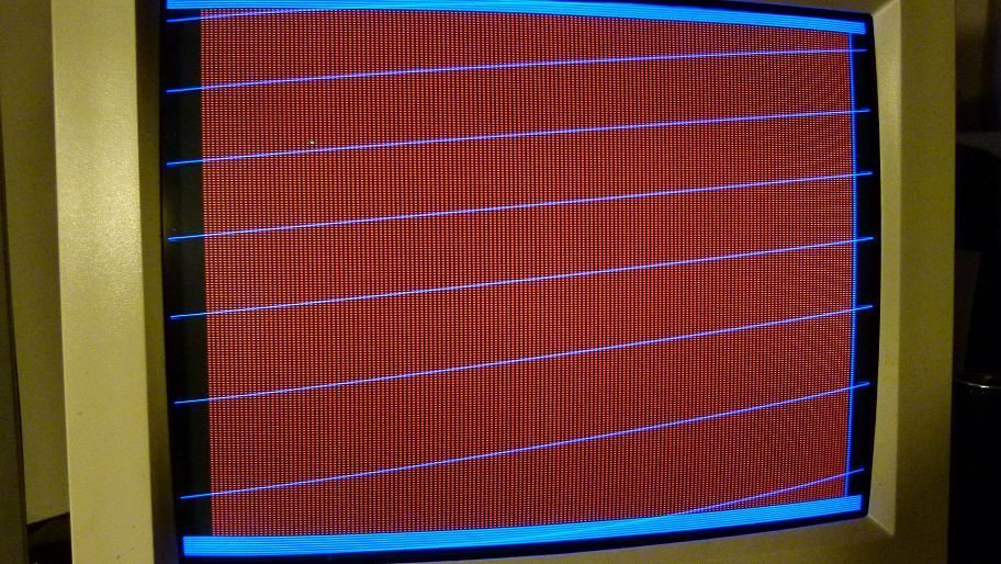
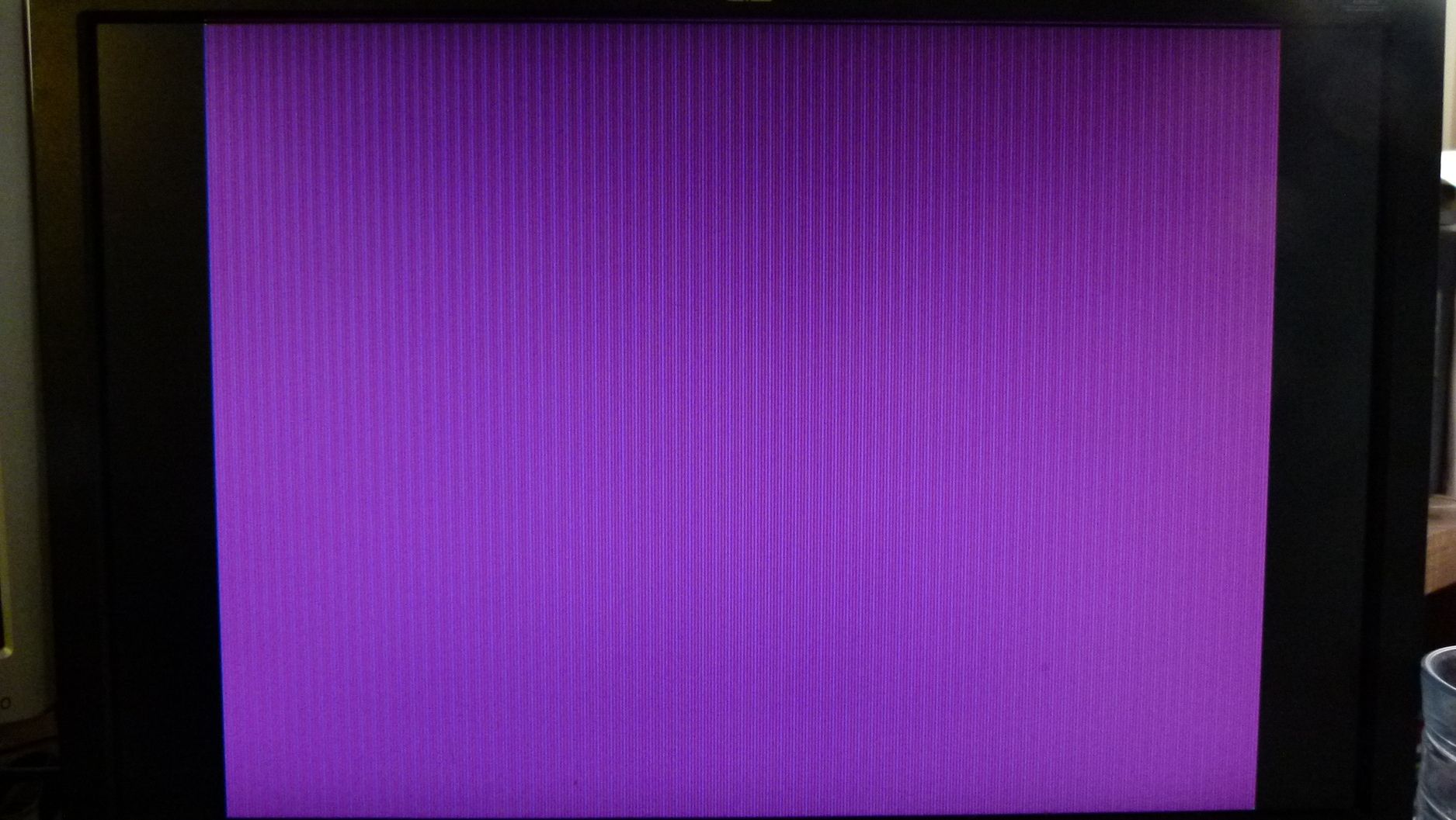
always @(posedge clk108) //outgoing data to videoDAC
if ( X == 49 & Y == 50 ) begin
Red_data <= 0;
Green_data <= 6'b111111;
Blue_data <= 0; //Priority 1, plot green pixel at (49,50)
end
else if ( !countflag ) begin
Red_data <= 0;
Green_data <= 0;
Blue_data <= 5'b11111; //Priority 2, blue border
end
else if ( X[0] ) begin
Red_data <= 5'b11111;
Green_data <= 0;
Blue_data <= 0; //Priority 3, odd pixels red
end
else begin
Red_data <= 0;
Green_data <= 0;
Blue_data <= 0; //Priority 4, even pixels black
end
endmodule
