Bus amplifiers and terminators
-
GARTHWILSON

- Forum Moderator
- Posts: 8775
- Joined: 30 Aug 2002
- Location: Southern California
- Contact:
Re: Bus amplifiers and terminators
Since your transmission lines' characteristic impedances are likely to be a tiny fraction of 4.7K (like 50 to 200 ohms), 4.7K won't really have any effect. If you do that kind of thing with lower resistances though, use the dual-resistor thing I mentioned with links about 8 posts up, with one resistor to ground and one to Vcc.
http://WilsonMinesCo.com/ lots of 6502 resources
The "second front page" is http://wilsonminesco.com/links.html .
What's an additional VIA among friends, anyhow?
The "second front page" is http://wilsonminesco.com/links.html .
What's an additional VIA among friends, anyhow?

Re: Bus amplifiers and terminators
Than i should put a constant voltage of lets say 1.5V on the backplane?
-
GARTHWILSON
- Forum Moderator
- Posts: 8775
- Joined: 30 Aug 2002
- Location: Southern California
- Contact:
Re: Bus amplifiers and terminators
That would reduce the number of terminating resistors required, but you'd have to be sure it's well bypassed to ground everywhere the terminating resistors connect to it, unless it's another plane layer, making for more layers in the board. If you really want to do terminations right so they actually do significant good, you will have to get into some transmission-line theory and do the calculations to control the characteristic impedances of the various lines and the possible discontinuities produced by connectors, loads that are scattered along the length of the line, etc., then make sure everything that drives the bus from either end (or any point in between) will have adequate strength. I don't want to be discouraging, just realistic about the size of the project. If you're up to studying it in adequate depth, you will go further in your projects and be able to help others too. Most hobbyists however will decide that it's a little too heavy for them, and just decide to keep the connections lengths shorter and the rise times slower so they can be successful at their own lower level of engineering abilities.
http://WilsonMinesCo.com/ lots of 6502 resources
The "second front page" is http://wilsonminesco.com/links.html .
What's an additional VIA among friends, anyhow?
The "second front page" is http://wilsonminesco.com/links.html .
What's an additional VIA among friends, anyhow?
Re: Bus amplifiers and terminators
Hmm, i could try, but it will be tricky, since i have 5 sockets along the backplane, and each socket connects to a different hardware, so how could i get around this issue?
Re: Bus amplifiers and terminators
Ok, lets try get some basic data. The backplane is exactly 1cm away from the chassis, which is a huge ground plane. the stripboard is long 16cm and the lines are ~1.5mm wide, with a ~0.5mm air gap between, and ~0.2mm high. There are 6 bus plugs, the first is for the cpu, second for the crtc, and 4 for peripherals, and you can assume that they are equally distanced. The clock is 4MHz, whitch is ~75M, if it were sine wave... And this is going to be tricky isn't it? 
-
GARTHWILSON
- Forum Moderator
- Posts: 8775
- Joined: 30 Aug 2002
- Location: Southern California
- Contact:
Re: Bus amplifiers and terminators
Quote:
Hmm, i could try, but it will be tricky, since i have 5 sockets along the backplane, and each socket connects to a different hardware, so how could i get around this issue?
I don't think you can get around it (as in avoiding the natural laws). We have the "Bus termination" topic at viewtopic.php?p=13073#13073, and Dr. Howard Johnson has a lot of related articles at https://web.archive.org/web/20120302190 ... eyword.htm and a couple of books, "High-Speed Digital Design" and "High-speed Signal Propagation" at http://www.sigcon.com/Pubs/index.htm. An engineer or engineering student such as yourself should not find it impossible to get through—just a bit time-consuming to familiarize oneself with the non-obvious but very real behavior that takes place in these circuits. The alternative of course is to keep few enough inches or cm of line length per ns of rise time that you don't have to go to such extremes. It shouldn't be difficult at the 4MHz frequency you're talking about. When you read through the material, if you find Dr. Johnson's rule of thumb again for how many inches or cm you can have per ns of rise time before transmission lines become important, please post it. I can't remember for sure, and I couldnt' find it again when I was looking recently. I know it's there though.
Quote:
Ok, lets try get some basic data. The backplane is exactly 1cm away from the chassis, which is a huge ground plane. the stripboard is long 16cm and the lines are ~1.5mm wide, with a ~0.5mm air gap between, and ~0.2mm high.
The transmission-line impedance will also depend on how far away the ground plane is from the traces, which means that if you have a multilayer board, you will have to specify the separation between layers instead of accepting just any random combination of thicknesses they give you to stack up to .062" total.
Quote:
There are 6 bus plugs, the first is for the cpu, second for the crtc, and 4 for peripherals, and you can assume that they are equally distanced.
and the various boards plugged into the backplane will also have some connection length, like stubs of a few cm.
http://WilsonMinesCo.com/ lots of 6502 resources
The "second front page" is http://wilsonminesco.com/links.html .
What's an additional VIA among friends, anyhow?
The "second front page" is http://wilsonminesco.com/links.html .
What's an additional VIA among friends, anyhow?
Re: Bus amplifiers and terminators
Ill take a look at toes documents. I don't have any multilayer pcb, just a 1cm gap between the bus and chassis. I could assume that every plugged module has internal wiring that goes for lets say 5cm (some modules have the bidirectional tristate ic, some don't).
Google link that i found: http://ece.uprm.edu/~mjimenez/inel6079/ ... niques.pdf
On page 6 there is a scenario based "SELECTION GUIDE FOR TERMINATION TECHNIQUES".
For "Driving a backplane with tristatable devices" the table recommends Schottky diodes.
Google link that i found: http://ece.uprm.edu/~mjimenez/inel6079/ ... niques.pdf
On page 6 there is a scenario based "SELECTION GUIDE FOR TERMINATION TECHNIQUES".
For "Driving a backplane with tristatable devices" the table recommends Schottky diodes.
-
BigDumbDinosaur

- Posts: 9428
- Joined: 28 May 2009
- Location: Midwestern USA (JB Pritzker’s dystopia)
- Contact:
Re: Bus amplifiers and terminators
GARTHWILSON wrote:
I don't think you can get around it (as in avoiding the natural laws). We have the "Bus termination" topic at viewtopic.php?p=13073#13073, and Dr. Howard Johnson has a lot of related articles at http://www.sigcon.com/Pubs/pubsKeyword.htm and a couple of books, "High-Speed Digital Design" and "High-speed Signal Propagation" at http://www.sigcon.com/Pubs/index.htm.
I was going to suggest that, but yuh beat me to it. A lot of these design issues have been sorted out over the years and if you can't find out about it in Dr. Johnson's writings, well, no one knows about it then.
As for terminating your bus, my suggestion for testing purposes would be to use Thevenin termination, which you can implement by pulling each line up to Vcc (5 volts) with a 220 ohm resistor and also down to ground with a 330 ohm resistor. The effective impedance will be approximately 132 ohms, which should be close enough for the speeds at which you are working. The resistors should be after the last receptacle on the backplane, but as close to that receptacle as practical. Bourns makes resistor networks with the correct values, which will simplify construction. The part numbers are 4610R-101-221LF (220 ohms) and 4610R-101-331LF (330 ohms), and both parts fit standard 2.54mm pin spacing. There are nine resistors in each network. I use these as SCSI bus terminators on my POC's host adapter and scoping the lines shows that the bus is dead quiet.
Quote:
...and the various boards plugged into the backplane will also have some connection length, like stubs of a few cm.
Sometimes the stubs cause more trouble than the main part of the bus. In my (fairly extensive) studies of SCSI over the years, I've noted where device manufacturers have gone to considerable lengths (!) to keep the stubs from the bus to the device's embedded controller logic as short as possible, usually millimeters. Reflections often occur on stubs of the intermediate devices in a SCSI daisy-chain, because those devices are not terminated. The ANSI X3-131 standard recommended no more than 10 centimeters for stubs (about 4 inches). However, that was when the bus speed topped out at 5 MB/second, effectively a 5 MHz rate. As the bus speed was increased, the stub length became a critical issue, resulting in vendors placing the embedded control silicon immediately adjacent to the cable connector. It also helped that around that time bus drivers had gotten a lot stronger.
Quote:
The lower drive current will be ok for CMOS-only loads where the only current is what's needed to charge the load capacitance, and the idea was partly to do it more slowly to make it friendlier for design and construction that is not suitable for high speeds. ABT is great, but in this case, coupled with the long lines he's talking about it might be kind of like starting a child on on a very high-powered motorcycle for his first one-- not recommended.
Either 74AC or 74ABT should work okay. I definitely would not use 74HC to drive a backplane bus. The bus capacitance will round off the switching waveform to an unacceptable degree, possibly causing some devices to get unstable as the voltage lazily slides up and down through "no man's land." A "stiff" driver will help to negate reactive effects, especially capacitance, because the driver has a low effective impedance, resulting in a very short time-constant. Most CMOS logic is not very tolerant of lazy transitions, so my opinion is drive the bus as hard as possible.
Quote:
In looking up the numbers in my National Semiconductor books though, I found it interesting that the 74AC245 had ten times the drive current of 74HC245 (75mA sink and source, compared to 7.5mA).
That's why I keep saying don't use 74LS or 74HC logic in new designs. It's like putting bicycle tires on a Harley drag motorcycle.
x86? We ain't got no x86. We don't NEED no stinking x86!
-
GARTHWILSON
- Forum Moderator
- Posts: 8775
- Joined: 30 Aug 2002
- Location: Southern California
- Contact:
Re: Bus amplifiers and terminators
The problem with the ABT here would be the edges being too fast for the construction type. And when he said there's no ground plane, only a chassis 1cm away (which, Dajgoro, does not qualify as a ground plane for transmission-line purposes-- not at all!), I realized we are just dealing with a bunch of parallel antennas, and termination science goes out the window. Now Dajgoro I think you're going to have to just keep to the recommended ratio of length to ns of rise time for unterminated lines. I wish I could find that ratio again. It seems like it was a few inches per ns, and hopefully 74AC would be fine. My book doesn't have an output slew-rate spec. on the 74AC245. Maybe you can find one online.
http://WilsonMinesCo.com/ lots of 6502 resources
The "second front page" is http://wilsonminesco.com/links.html .
What's an additional VIA among friends, anyhow?
The "second front page" is http://wilsonminesco.com/links.html .
What's an additional VIA among friends, anyhow?
-
BigDumbDinosaur
- Posts: 9428
- Joined: 28 May 2009
- Location: Midwestern USA (JB Pritzker’s dystopia)
- Contact:
Re: Bus amplifiers and terminators
GARTHWILSON wrote:
The problem with the ABT here would be the edges being too fast for the construction type. And when he said there's no ground plane, only a chassis 1cm away (which, Dajgoro, does not qualify as a ground plane for transmission-line purposes-- not at all!), I realized we are just dealing with a bunch of parallel antennas, and termination science goes out the window. Now Dajgoro I think you're going to have to just keep to the recommended ratio of length to ns of rise time for unterminated lines. I wish I could find that ratio again. It seems like it was a few inches per ns, and hopefully 74AC would be fine. My book doesn't have an output slew-rate spec. on the 74AC245. Maybe you can find one online.
TI says slew rate for the AC245 is 3ns, measured from high being 90 percent of Vcc and low being 10 percent of Vcc (data sheet here).
x86? We ain't got no x86. We don't NEED no stinking x86!

Re: Bus amplifiers and terminators
I calculated an estimate of this ratio based strictly on the signal propagation speed in the material (FR4/G10), and I get a value of approximately 68 mm/ns, or 2.7 in/ns.
This estimate does not consider any effects from distributed capacitance or inductance along the signal path, or lumped capacitance at line loads. Rather, the estimate is based on a simple line length estimate for a far end reflection to return to the source end within the rise time interval. The fact that the effects of distributed capacitance and lumped load capacitance are not considered will be result in an estimated line length that is too long. However, it should provide an adequate estimate for simple designs.
On the issue of chassis as a ground plane for the backplane, I agree with Garth's assessment. I will say that the ladder line being used is not likely to operate in an edge coupled transmission line mode with adjacent ladder lines. I also suspect that because there is no ground or power plane, the effective dielectric constant will likely be around 2 instead of 4.8. This means that the estimated line length limit will double, but it also means that the transmission line impedance will increase toward the 377 Ohm limit of a wire in free space.
Michael A.
Re: Bus amplifiers and terminators
What if i were to glue a grounded aluminum foil to the bus? Or do you have a batter suggestions on how to build a ground plane?
The backplane stripboard is identical as in this image:
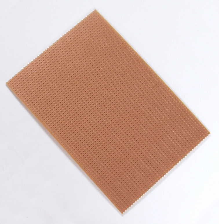
Except, i placed a tin layer over it.
The backplane stripboard is identical as in this image:
Except, i placed a tin layer over it.

Re: Bus amplifiers and terminators
Something bothering me here. BDD keeps wanting to drive busses as hard as possible, which means ever faster edges. But this ratio implies that on a longer bus you need to have slower edges. It makes sense to me, because as Michael points out, the aim with transmission lines is not to have the edges multiply up as they rattle from one end to the other. It might be OK for a data signal but would be a killer for a clock or strobe.
Similarly, Garth points out that we have more of a crosstalk problem here than a reflections problem: again, slower edges would help.
As I understand it - and I'm not expert - you want enough drive to get your lines to valid levels at the point they are clocked. You want your clock or strobe edges to be fast enough that you don't have too much delay from the slew time, and indeed as BDD says you want all edges fast enough not to be dithering near a threshold at the wrong time.
But beyond those points, you actually want not to have faster edges. In a sense you want the slowest edges which satisfy the above constraints. Isn't that so?
Cheers
Ed
-
GARTHWILSON
- Forum Moderator
- Posts: 8775
- Joined: 30 Aug 2002
- Location: Southern California
- Contact:
Re: Bus amplifiers and terminators
That's about right, Ed. I've been looking for good diagrams and animations online that I could post links to, showing the matters of mutual inductance and ground planes, but I have not found any so far. There are some sort-of good ones about transmission lines in Dr. Johnson's articles, but I was especially looking for ones that relate to lines that are shorter relative to the slew rate but still plenty long to cause trouble with things like crosstalk, inductance, and noise both radiated & picked up, all able to foul up signals to the point of non-operation.
I have developed a pretty good feel for what goes on in this field, but I'm far from being an expert in it. I don't have much experience that would tell where you're really on the edge of trouble. No one really wants to take the time to build complex projects that intentionally may not work, just to find out where that edge is. Whatever one has built that does work however can be evaluated to some extent with an oscilloscope of suitable speed to see what's going on. I built my workbench computer before I understood this stuff nearly as well as I do now, and some of its signals look atrocious on the 'scope-- and they don't even go off the board. Fortunately it works anyway. I added the A/D and D/A converters later and did much better on the grounding scheme there, and they don't have any noise problems for 8-bit converters. Related experience I have is with switching power supplies, and I have been on the edge there-- not that any totally failed to work, but they get noisy with pulse-skipping, jitter, etc. when things like proper ground practices, trace & lead inductance, and mutual inductance are not understood and observed. That may not be a problem for powering digital-only circuits, but we are using them for high-quality audio where the added noise is not acceptable even if the circuit works.
For the proto board with the strips: Sticking the aluminum foil down on the opposite side with double-stick tape should work fine for a ground plane; but I see a couple of challenges with it: 1., keeping signal and other non-ground pins that go through the holes from touching the foil around them where they're not supposed to; and 2., connecting to the aluminum, since you can't solder to it, and some type of good pressure contact would be needed.
To really fulfill the purpose, you would need many such connections to the ground plane, none of them being very far from where each individual signal line connects from each card to the back plane. STD bus worked ok at 2MHz with LS speeds and the ground connections at one end of the connector, but I don't think you would have to get much faster before you would start running into trouble. Just having one or two ground connections per card will no longer do the job.
In the realm of what is practical to construct using the proto board with the strips, what would work best is if every 2nd strip were ground, and every card would bring all those ground connections through. If that takes away too many strips, the make every 3rd strip ground, so at least there's a ground strip on one side next to every signal strip.
If I can't find diagrams online showing some of the ideas we keep talking about in text, I ought to draw them for the sticky topic "Techniques for reliable high-speed digital circuits" and for my website. I can't take the time right now, so it will have to wait.
http://WilsonMinesCo.com/ lots of 6502 resources
The "second front page" is http://wilsonminesco.com/links.html .
What's an additional VIA among friends, anyhow?
The "second front page" is http://wilsonminesco.com/links.html .
What's an additional VIA among friends, anyhow?
-
BigDumbDinosaur
- Posts: 9428
- Joined: 28 May 2009
- Location: Midwestern USA (JB Pritzker’s dystopia)
- Contact:
Re: Bus amplifiers and terminators
BigEd wrote:
Something bothering me here. BDD keeps wanting to drive busses as hard as possible, which means ever faster edges.
Not necessarily. By "hard" I mean sourcing and sinking enough current to reduce deviations from the ideal rectangular waveform that devices expect to see at input. However, the ability of a driver to source or sink high current doesn't automatically imply that it is a fast-switching device. Power transistors of the type used in audio amplifiers are able to source and sink high current, but aren't particularly fast at switching from one state to the other.
In a typical bus (e.g., address or data bus on your computer's mainboard), some of the drive is needed to charge or discharge device input capacitance. However, in a bus of any reasonable length, it's likely that much distributed capacitance will be present, which also has to be charged or discharged by the driver. If the driver is "soft" then the effective RC time-constant seen on the bus is "high" (in a relative sense) and transitions are lazy. Plus the farther way the driven device is from the driver, the longer the effective propagation time, not because of the physical wire length, but due to the fact that current always leads voltage in a predominantly capacitive scenario. If the driver is "hard" then the effective RC time-constant is "low," transitions are well-defined and the driven devices are not forced to dwell in their "no man's land" for any significant time.
Consider that a 74AC138 decoder has a Δt/Δv specification of 20ns per input volt when operated at 5 volts. At 5 volts, Vih is 3.85 minimum and Vil is 1.65 maximum, so the "no man's land" range is 2.2 volts. Hence the maximum allowable time for an input transition to occur is 44ns without violating Δt/Δv. If a device with an 'AC138 is at the far end of the bus and the device driving the bus is "soft," at best the 'AC138's reaction to bus events will be skewed. At worse, reaction will be skewed and Δt/Δv will be violated.
So I'm not saying edges have to be extremely fast, but fast enough to satisfy the Δt/Δv of the slowest device on the bus, after accounting for the delays caused by distributed capacitance.
x86? We ain't got no x86. We don't NEED no stinking x86!