Hi there,
for some years I have been working on and with my CS/A computer (see http://www.6502.org/users/andre/csa/index.html ) that can run at 1MHz or 2MHz. Testing at 2MHz has always been a bit difficult, there were some - to me at least - unexplainable effects.
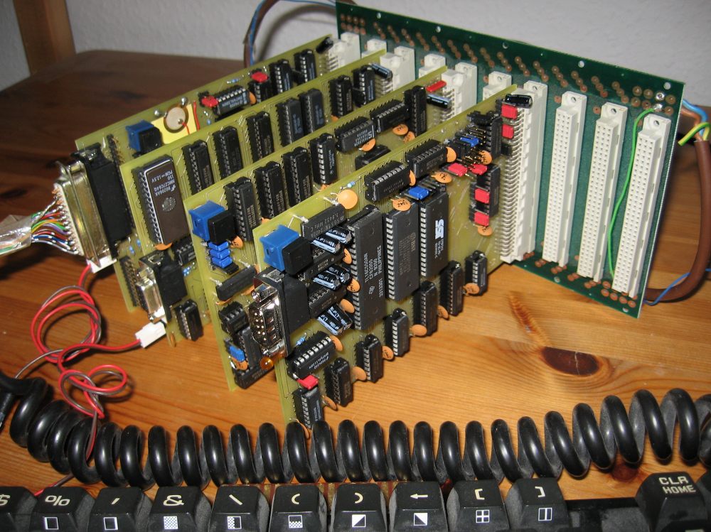
I am using a passive backplane (for a picture see the link above or http://www.6502.org/users/andre/csa/gallery/caspaer.jpg ) and while debugging my RAMdisk board I found that the CPLD actually receives glitches from the system bus at 2MHz. I.e. the address lines are not stable but the CPLD sees it sometimes changing from 1 to 0 when it shouldn't, especially during phi2.
So I decided to look into bus design and bus termination and found this article http://www.retrotechnology.com/herbs_stuff/s_term.html about the S100 bus, which is as far as I understand very similar to a 6502 in terms of electrical characteristics. My bus is basically just that, a 6502 bus driven mostly by '245 TTL drivers.
Scoping the DRAM address lines on my RAMdisk board showed me how well termination resistors can work in reducing jitter on the signals, so I decided to build a termination board for the backplane, with passive terminators (each signal has a resistor to VCC and to GND). What I am not sure about is the value of those resistors.
I sometimes see 220/330 Ohm pairs, which will level the line at 2V, sometimes I read to use "the middle between logic 0 and 1" - which would be lower for TTL. In other parts I read that these resistors put some serious load on the power supply and possibly the drivers, at least for large number of terminated signals. I'm going to order me sets of resistor networks with different values so I can experiment with them and see what is best.
What is your take on bus termination? What busses do you use and to what frequency?
André
Bus termination...
-
BigDumbDinosaur

- Posts: 9426
- Joined: 28 May 2009
- Location: Midwestern USA (JB Pritzker’s dystopia)
- Contact:
Re: Bus termination...
fachat wrote:
What is your take on bus termination? What busses do you use and to what frequency?
Any open-ended bus like the S-100 (or SCSI, for that matter) will experience reflections. Reflections are not necessarily related to bus speed, but become a major issue when their period approximately coincides with the bus' switching rate. This is probably what you are experiencing.
Active termination may help. However, it's my not-totally-uneducated opinion that it will only be a band-aid solution. What I think is happening is you are suffering from the effects of scale. One or two sockets on the backplane, along with one or two cards is no big deal. However, you have 10 sockets, which means you have a lot of traces on the PCB, each adding its stray capacitance and series inductance to the circuit. An analogy to the straw that broke the camel's back is almost unavoidable. Accordingly, here are some thoughts in no particular order:
- Passive Backplane
By definition, if it's passive it's basically just an organized bunch of wires, not too unlike an early version of a telephone cable (in the days before balanced-to-ground circuitry was adopted). With that much wire, reactive effects are unavoidable, and as you know, increase with the square of the frequency (or switching speed), and (more-or-less) linearly with bus length and total connections. One of the reasons modern computers use closely-spaced card edge connectors instead of pin connectors to attach expansion cards to the bus is because of the pin connectors' more pronounced reactive effects. Consider all those sockets on your backplane. Now, look at all those header pins on the expansion cards. That's a whole bunch of capacitance and inductance just waiting to generate ringing and other annoyances. Combine that with the generally modest drive capability of the average 74LS device (see next) and you have the near-ideal combination of circumstances to cause bus havoc.
The obvious solution would be to design a new series of cards that use edge connectors (2.54 mm pitch type, most likely) and reduce bus stub lengths to the absolute minimum. Also, take a tip from the PC world, specifically the PCI bus. The most number of PCI slots you will see in modern practice is six, and those are on much closer centers (0.800 in/20.32 mm) than the connectors on your backplane. - 74LS Logic
Along with improved speed over the original 74-series logic, 74S hardware was noted for generally good noise immunity, but was also criticized for high power consumption. 74LS addressed the latter but also compromised the former. I recall 25-30 years ago that much of the effort that went into designing anything with 74LS logic was expended on trying to keep a lid on switching noise and other assorted glitches. The transition to CMOS logic did a lot to improve the noise issue, albeit at the expense of performance in the first CMOS families. Once the 74HC series became available, the use of 74LS in new designs rapidly subsided.
The irony is 74LS is very noisy (one of the reasons why each chip needs a decoupling cap) and is often its own worst enemy. Have you considered using more robust bus drivers from the 74ABT family? Their output is much "stiffer" than what you can get from 74LS parts, which can do a lot to minimize glitches that actually may be a result of lazy voltage level transitions. Ultimately, what you are trying to do is rapidly charge and discharge the bus capacitance through bus inductance and resistance. Your drivers and/or transceivers need to be able to overwhelm these effects. Take a look at parts like the 74ABT245 (octal transceiver) and 74ABT541(octal buffer) for driving the bus. A bonus with these parts is their single nanosecond propagation time (characteristic of all 74ABT devices). - Expansion Card Count
Here again, a look at contemporary PC technology is instructive. 25 years ago, the typical PC motherboard had zero I/O capability. Anything and everything got connected through an expansion card (on the ISA bus, of course). The notion was that the board shouldn't incorporate any features that weren't wanted. That philosophy made sense in those days due to the high cost of computer hardware of any kind.
However, a funny thing happened on the way to increasing performance. All those cards made it difficult to achieve high switching speeds. The solution came in several steps, the first being the transition to CMOS logic to get around all the noise issues, the second being the integration into the motherboard of some features that were usually provisioned on cards (e.g., floppy and hard disk ports). As integration increased, so did performance. As a bonus, cost went down. Now we're at the point where the modern PC's expansion bus runs faster than the microprocessors that existed when the PCI bus was developed.
It might be worthwhile for you to consider this. I see where you've developed a lot of stuff that runs on plug-in cards. However, all those cards are placing lots of reactance into the circuitry, as well as demanding a lot of drive. You know that there are some basic I/O features that you are going to need no matter what. Those should be integrated into a motherboard. Optional features, such as an Ethernet port, could remain on an expansion card.
Summed up, my opinion is you have too much stuff hanging off your bus.
x86? We ain't got no x86. We don't NEED no stinking x86!
-
GARTHWILSON

- Forum Moderator
- Posts: 8773
- Joined: 30 Aug 2002
- Location: Southern California
- Contact:
The problem with reflections and the need for termination is associated with rise and fall times, not particularly frequency. The faster the t(r), the shorter the maximum transmission line length needs to be to avoid problems. Dr. Howard Johnson has a lot of articles on it linked here. I was going to list the most relevant ones separately, but there are too many. He is quite an industry guru on this stuff.
http://WilsonMinesCo.com/ lots of 6502 resources
The "second front page" is http://wilsonminesco.com/links.html .
What's an additional VIA among friends, anyhow?
The "second front page" is http://wilsonminesco.com/links.html .
What's an additional VIA among friends, anyhow?
-
BigDumbDinosaur
- Posts: 9426
- Joined: 28 May 2009
- Location: Midwestern USA (JB Pritzker’s dystopia)
- Contact:
Upon reflection...
GARTHWILSON wrote:
The problem with reflections and the need for termination is associated with rise and fall times, not particularly frequency.
That said, the effects of lazy transitions get exacerbated on a bus with significant line length and/or loading. André's backplane is probably the guilty party in this reqard.
Quote:
The faster the t(r), the shorter the maximum transmission line length needs to be to avoid problems. Dr. Howard Johnson has a lot of articles on it linked here. I was going to list the most relevant ones separately, but there are too many. He is quite an industry guru on this stuff.
x86? We ain't got no x86. We don't NEED no stinking x86!
GARTHWILSON wrote:
The problem with reflections and the need for termination is associated with rise and fall times, not particularly frequency. The faster the t(r), the shorter the maximum transmission line length needs to be to avoid problems. Dr. Howard Johnson has a lot of articles on it linked here. I was going to list the most relevant ones separately, but there are too many. He is quite an industry guru on this stuff.
I was also thinking about the rise and fall times as a particular reason for the noise, as sometimes using a ALS type made it worse compared to an LS type.
I know very well that my stuff is horribly outdated :-) But I actually started that whole thing in 1989, so back then, it wasn't really outdated ;-) Then I jumped on and off that project over the years...
But with the dying of 5V parts, especially the higher integrated ones, I feel I need to do a big cut very soon anyway. I have three projects still in the pipeline (Ethernet, I hope to get that done these days, board's done, working on the driver, a block transfer engine, and USB, but I may postpone the latter until after the switch). Until then I hope I have my 65k CPU ironed out into a working state, so then I'm going to switch to an all-new design, FPGA, high speed, 3.3V, maybe even lower, and so on. No details defined yet though.
For me this system is more about self-education and the love of tinkering with stuff. So now I'm going to educate myself about bus termination ;-)
Thanks for your comments
André
WOW, I never realized that a bus should be terminated at Vcc/2. But, it makes perfect sense, looking at it from a ham radio point of view. This would explain all the bizarro voltages (e.g., 0.9V for a 1.2V to 1.8V system) you see on DDR2-SDRAM chips these days.
On the other hand, it also supports the strong desire for both serial and unidirectional, point to point links like SPI and HyperTransport. Fewer lines means reduced hardware for termination, and hence, reduced idle draw on the power supply.
This actually gives me some WICKED expansion ideas.
On the other hand, it also supports the strong desire for both serial and unidirectional, point to point links like SPI and HyperTransport.
This actually gives me some WICKED expansion ideas.
GARTHWILSON wrote:
The problem with reflections and the need for termination is associated with rise and fall times, not particularly frequency. The faster the t(r), the shorter the maximum transmission line length needs to be to avoid problems. Dr. Howard Johnson has a lot of articles on it linked here. I was going to list the most relevant ones separately, but there are too many. He is quite an industry guru on this stuff.
I just computed the minimal series termination Zmin for an LS245 from its nominal voltage and current spreads:
Zmin = (Voh-Vol)/(Ioh-Iol)
which for the 'LS245 turns out to be
Zminls245 = (2.4V-0.4V)/(3mA+12mA) = 133 Ohm
Now looking at the split-resistor termination, with R1 going to VCC and R2 going to GND, the parallel resistor formula holds for the impedance Z:
Z = 1/(1/R1 + 1/R2) = 132 Ohm
Suprise, surprise :-)
At least now I know where these values come from. According to Dr. Johnson "The optimal value for the termination resistance is just a little higher than the minimum impedance to account for tolerances, ..."
I guess the tolerances allow for the max load specs of the LS245, where
Zminls245max = (2V - 0.5V)/(15mA + 24mA) = 37.5 Ohm.
So that explains why the 330/220 Ohm combination is chosen that often... Enough reason to try it myself :-)
http://www.sigcon.com/Pubs/edn/zmin.htm
André
-
ElEctric_EyE
- Posts: 3260
- Joined: 02 Mar 2009
- Location: OH, USA
-
BigDumbDinosaur
- Posts: 9426
- Joined: 28 May 2009
- Location: Midwestern USA (JB Pritzker’s dystopia)
- Contact:
fachat wrote:
I just computed the minimal series termination Zmin for an LS245 from its nominal voltage and current spreads:
Zmin = (Voh-Vol)/(Ioh-Iol)
which for the 'LS245 turns out to be
Zminls245 = (2.4V-0.4V)/(3mA+12mA) = 133 Ohm
Now looking at the split-resistor termination, with R1 going to VCC and R2 going to GND, the parallel resistor formula holds for the impedance Z:
Z = 1/(1/R1 + 1/R2) = 132 Ohm
Suprise, surprise
At least now I know where these values come from. According to Dr. Johnson "The optimal value for the termination resistance is just a little higher than the minimum impedance to account for tolerances, ..."
I guess the tolerances allow for the max load specs of the LS245, where
Zminls245max = (2V - 0.5V)/(15mA + 24mA) = 37.5 Ohm.
So that explains why the 330/220 Ohm combination is chosen that often... Enough reason to try it myself
http://www.sigcon.com/Pubs/edn/zmin.htm
André
x86? We ain't got no x86. We don't NEED no stinking x86!
BigDumbDinosaur wrote:
BTW, the 74ABT245 can source or sink twice the current of the LS245. That can do a lot to clean up your buses.
André
-
BigDumbDinosaur
- Posts: 9426
- Joined: 28 May 2009
- Location: Midwestern USA (JB Pritzker’s dystopia)
- Contact:
Where have all the DIPs gone?
fachat wrote:
BigDumbDinosaur wrote:
BTW, the 74ABT245 can source or sink twice the current of the LS245. That can do a lot to clean up your buses.
André
x86? We ain't got no x86. We don't NEED no stinking x86!
-
GARTHWILSON
- Forum Moderator
- Posts: 8773
- Joined: 30 Aug 2002
- Location: Southern California
- Contact:
Re: Bus termination...
Looking over this again, I see the transmission line characteristic impedance Z0 was not really addressed. That, and not the source, is what really needs the termination. The reflected edges will bounce back and forth off the ends if the load does not match the Z0 of the transmission line. (If it's monodirectional and the load end is terminated in the proper impedance, it will not reflect any energy back to the source, so the impedance at the source won't matter as long as it's low enough to drive the load hard enough.)
There's a PCB transmission-line calculator at https://www.eeweb.com/tools/microstrip/ that you can use to figure out how wide your PCB traces should be (assuming you have a real ground plane) to get the target impedance.
In this article, Dr. Howard Johnson says,
The trace delay time is approximately the trace length (including going through well behaved connectors) divided by the speed of light, divided by approximately .65 since the phase propagation velocity of a transmission line in the FR-4 PCB material is approximately .65 times the speed of light. I don't remember the exact number, but I know that's close. So if a trace were 20cm long, you would have
.2m / 300Mm/s / .65 = 1ns (approximately)
In my NSC data book for 74ABT, it looks like the rise (and fall) time is typically 2ns, but the minimum prop delay (which includes the rise time) is sometimes only 0.8ns, meaning you would be terminating lines down to about 15cm total length. But! Remember he said many take the more conservative approach of terminating if it's more than 1/4 or even 1/6 of that length, meaning that yes, they would terminate 20cm even with LS or HC, and terminate a line as little as 3cm long if it's fed with ABT.
Uh-oh, André, I just looked at your picture at http://www.6502.org/users/andre/csa/gallery/caspaer.jpg, and although it's very nice construction, it looks like you may be way over the 20cm I picked arbitrarily for the example, but that's almost irrelevant because it looks like you don't have a ground plane, at least not on the plug-in boards, meaning you don't have real transmission lines let alone any control of their characteristic impedance. What's the latest on the project?
There's a PCB transmission-line calculator at https://www.eeweb.com/tools/microstrip/ that you can use to figure out how wide your PCB traces should be (assuming you have a real ground plane) to get the target impedance.
In this article, Dr. Howard Johnson says,
Quote:
"How do you know when a terminator is needed? The ratio of trace delay to rise time is the first clue. Terminations are almost always required when the trace delay exceeds the logic rise time. Many people take an even more conservative approach, installing terminations when trace delay exceeds one-fourth, or even one-sixth, of the logic rise time."
.2m / 300Mm/s / .65 = 1ns (approximately)
In my NSC data book for 74ABT, it looks like the rise (and fall) time is typically 2ns, but the minimum prop delay (which includes the rise time) is sometimes only 0.8ns, meaning you would be terminating lines down to about 15cm total length. But! Remember he said many take the more conservative approach of terminating if it's more than 1/4 or even 1/6 of that length, meaning that yes, they would terminate 20cm even with LS or HC, and terminate a line as little as 3cm long if it's fed with ABT.
Uh-oh, André, I just looked at your picture at http://www.6502.org/users/andre/csa/gallery/caspaer.jpg, and although it's very nice construction, it looks like you may be way over the 20cm I picked arbitrarily for the example, but that's almost irrelevant because it looks like you don't have a ground plane, at least not on the plug-in boards, meaning you don't have real transmission lines let alone any control of their characteristic impedance. What's the latest on the project?
http://WilsonMinesCo.com/ lots of 6502 resources
The "second front page" is http://wilsonminesco.com/links.html .
What's an additional VIA among friends, anyhow?
The "second front page" is http://wilsonminesco.com/links.html .
What's an additional VIA among friends, anyhow?
Re: Bus termination...
GARTHWILSON wrote:
Uh-oh, André, I just looked at your picture at http://www.6502.org/users/andre/csa/gallery/caspaer.jpg, and although it's very nice construction, it looks like you may be way over the 20cm I picked arbitrarily for the example, but that's almost irrelevant because it looks like you don't have a ground plane, at least not on the plug-in boards, meaning you don't have real transmission lines let alone any control of their characteristic impedance. What's the latest on the project?
In fact it works - as long as you take slow chips, like LS. Once you get faster with ALS or HCT problems seem to creep in. Sensitive chips like CPLDs or such need buffers, esp. in Phi2.
I would not say I have "finished" this project, but it is close. My current (latest and probably last) board is an FPGA card where I want to experiment with my own 6502-based CPU. Once that is done, it goes into direction of a fast single-board computer that has just I/O go off the board, but no CPU clock/address/data lines.
André
Author of the GeckOS multitasking operating system, the usb65 stack, designer of the Micro-PET and many more 6502 content: http://6502.org/users/andre/
-
fredericsegard

- Posts: 47
- Joined: 05 Aug 2020
- Location: Montreal, QC, Canada
- Contact:
Re: Bus termination...
I know it's an old thread, but it's relevant to my current project. I'm in the process of designing a backplane using 62-pin ISA card edge connectors. It gives me plenty of pins to have a 65816 CPU board with all associated signals. I have 8 slots, 22mm on-center, and the total trace length from end to end is below 15cm. On the same board, I'm breaking out the signals to a 62-pin single-row header, so I can plug the backplane board directly on a BB830 breadboard for experimentation.
Trace width from one end of the bus to the other is .45mm. And trace width to the breakout header is .33mm. Power distribution trace width goes from 2.5mm to 1.6mm. It's a 4-layer board, where bus lines and some power distribution traces will be on the front layer, and the perpendicular bus lines to the breakout header are on the back layer. One of the inner layers is a VCC plane, and the other is a ground plane (or should they be both ground planes?). Front and back layers are also ground copper-filled.
After reading this thread, and trying to understand Dr. Johnson's articles (which went over my head, to be honest), I'm wondering if it will be pertinent to implement bus termination (in part because it's a relatively short bus). I plan on running my bus at 8HMz. If all my signals are properly driven with ABT family of chips, should I still consider termination? Do all signals benefit from termination? What seems to be popular is the resistor divider 330Ω-220Ω termination scheme. There's also the 2.85 V regulator with 220Ω series resistors to the signals may also be an option. What about normally pulled-up lines like /IRQ, /NMI, BE, etc?
- Attachments
-
-
-
GARTHWILSON
- Forum Moderator
- Posts: 8773
- Joined: 30 Aug 2002
- Location: Southern California
- Contact:
Re: Bus termination...
fredericsegard, no need to apologize for reviving an old topic. It will always be relevant.
See the 6502 primer's page about construction for good AC performance, at http://wilsonminesco.com/6502primer/construction.html . It has good links to lectures and articles about termination; but I also just expanded it to cover the matter of connector pinout, since you only have power and ground at the ends, something that is ok only for slow components.
See the 6502 primer's page about construction for good AC performance, at http://wilsonminesco.com/6502primer/construction.html . It has good links to lectures and articles about termination; but I also just expanded it to cover the matter of connector pinout, since you only have power and ground at the ends, something that is ok only for slow components.
http://WilsonMinesCo.com/ lots of 6502 resources
The "second front page" is http://wilsonminesco.com/links.html .
What's an additional VIA among friends, anyhow?
The "second front page" is http://wilsonminesco.com/links.html .
What's an additional VIA among friends, anyhow?