(Edited 4/10/23 to attach the images rather than link to externally hosted ones)
In the first page of the "Fast prototyping boards" topic under "General discussions," the subject of the lack of a standardized I²C pinout came up. Although I²C is is a widely adopted 2-wire synchronous-serial interface industry standard, it does not specify a connector. For the most part, there's no need for it to, as most I²C parts are on the same board with the controller and don't go through any connectors, or if they do, the connector might be handling plenty of other signals too. The difference in our case is that we want to be able to make modules that plug in, similar to the SD-card idea.
Our super-flexible 65SIB (6502.org serial interface bus, for connecting external devices with ribbon cable), which can be as simple or as intelligent as you want it to be, was developed to extend the usefulness of SPI and similar interfaces in several directions at once and to make it easier to share designs and perhaps even hardware in the future. Nothing about it requires 6502-related hardware; the "65" just credits this forum and website.
Similarly, it makes sense to standardize on an I²C connector, again to make it easier to share hardware. What I am proposing here is what Daryl already offers on his SBC-4 board, and he also offers a matching serial EEPROM module, $6 each with a 64Kx8 EERPOM and the socket. Here's an earlier half-postage-stamp-sized EEPROM modules shown here with only four pins:
EEPROMmodule.jpg (10.59 KiB) Viewed 9954 times
(Actually, the pins are on the computer board, and the socket is on the module.) The 4-position socket on the end has Pin1=data, Pin2=Vcc, Pin3=ground, and Pin4=clock, and Daryl and I agreed that all future I²C plugs and modules should use a 6-pin, with Pin5=IRQ\ for things like a keypad controller, RTC with alarms, etc., and one hole (position #6) blocked and Pin 6 cut off so you cannot plug the I²C device in upside down. The I²C interface method pretty much excludes the need for a RST\. My older four-pin ones will plug into the 6-pin header as long as I'm careful to put it on correctly, ie, right-side-up and leaving the IRQ\ pin exposed on the right end. Note: "IRQ\" does not necessarily mean it connects directly to your 6502/816's IRQ\ pin. One user asked if it would be ok to connect it to a VIA's CB1 pin. The answer is "Sure, just put a pull-up resistor on it." IRQ\ is common nomenclature (is that the right word?) for this kind of thing.
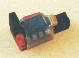
Edit, 7/28/22: I now have an I2C-6 EEPROM module is on the front page of my site, and there's a link to the data sheet there. I got hundreds of boards made, although my initial order of 24c256 EEPROMs was only for 25. I'll get more when needed.
assembledWM-5b.jpg (48.8 KiB) Viewed 9954 times
Here is the pinout, looking toward the master, into the edge of its board:
The pins could also be vertical if desired. Even with the keying, it would be good to mark pin 1 since it's not as clear with vertical pins. An example marking would be to put a dot or numeral "1" next to pin 1 in the silkscreened legend, or mark it with a marker.
I²C allows multi-master setups but I expect they're rare. A connecting cable could be made. Extension cables can be made for devices that may be too heavy to plug directly into the side of the controller board and be safely supported by the pins. "Y" adapters can also be made for connecting multiple devices to a single port which of course the I²C standard also allows, as long as no more than one device responds to any given address. Modules can optionally be made with the socket on one end to plug into the controller and a pin header on the back to daisychain another device.
I initially thought of putting "65" in the name again, something like "65I2C", just to credit our forum and website, but Daryl thought it would be too confusing (and I agreed), looking like "sixty-five-twelve-see," and could cause problems with searches even if we don't care how anyone actually pronounces it since we talk in text. He suggested "I2C-6" which sounds good to me.
I2CChip.com in Auckland, New Zealand (whose website has a load of good info on I²C) wanted to standardize on the 6-pin version of this subminiature connector shown here in 8-pin:
I2CChipConx.jpg (13.56 KiB) Viewed 9954 times
but it will not go into standard perfboard with holes on .100" centers. Totally by coincidence as far as I can remember, the pinout is the same as what's above. What is not a coincidence at all is that ours is intended to be easily breadboardable (on perfboard, not solderless breadboards).
Related and similar: On Oct 31, 2016, I proposed a hobbyist-friendly connector standard for small SPI modules, called SPI-10, at viewtopic.php?p=48167#p48167. My first application is for tiny 4MB and 8MB flash memory modules; but it can be used for all kinds of SPI circuits. SPI-10 does not in any way nullify 65SIB (mentioned in the 2nd paragraph of this post) which is a bus for multiple slaves, with auto addressing and other things that SPI-10 does not have. SPI-10 is for single-address modules that will usually be quite small.
search terms: I2C connector connection pins pin header socket standard
Last edited by GARTHWILSON on Wed Sep 28, 2016 1:12 am, edited 5 times in total.
While the pinout can be a standard for us to work with, Lee had a great little parallel to I2C capable of master/slave. Would we want to use that one or a CPLD version as a standard I2C for all our projects on here?
"My biggest dream in life? Building black plywood Habitrails"
His is a welcome addition, but if you want to use that and I continue to bit-bang for example, the same modules will still work for both if the connector type is standardized. He did not specify a connector type. I²C, because of its passive pull-ups, is not very fast, usually maxing out at 1Mbps, sometimes even 400kbps, so bit-banging doesn't present the bottleneck here like it does in SPI where some parts can go 50-100Mbps. [Edit, 2022: Some now are nearly 200Mbps.] I²C works well for when there's no need to go so fast, like a keyboard scanner, real-time clock, digital thermometer, D/A to set a power-supply voltage, etc.. As far as how you generate or read the signals, I don't see any need to standardize, unless we wanted to share software too. Writing I²C bit-banging software is almost trivial though. [Edit: I have sample code at http://wilsonminesco.com/6502primer/GENRLI2C.ASM .]
"Sharing hardware" as I mentioned earlier sounds like the early days of computers when the internet didn't exist yet and it was common to send floppy discs through the mail. Perhaps I should have clarified by linking to where I brought up the consortium idea for various ones of us making modules for the benefit of everyone building their projects at home: viewtopic.php?f=4&t=1656&start=52&hilit=consortium
(and the two posts after it)
What I am proposing here is what Daryl already offers on his SBC-4 board, and he also offers a matching serial EEPROM module, $6 for ten tiny bare PCBs. (You add the 24-series 8-pin-DIP EERPOM and the socket.) Here's an earlier half-postage-stamp-sized EEPROM modules shown here with only four pins:
Just to clarify, my modules are assembled with the 64k x 8 EEPROM. One sells for $6 and I have 10 of them available now, more can be provided.
I will sell the bare boards as well, contact me if you would like either, or would like more information.
Just to clarify, my modules are assembled with the 64k x 8 EEPROM. One sells for $6 and I have 10 of them available now, more can be provided.
I just went up and corrected my post. I apologize for having misunderstood. I see the new forum software gives a bar for telling the reason for the edit.
Just to clarify, my modules are assembled with the 64k x 8 EEPROM. One sells for $6 and I have 10 of them available now, more can be provided.
I just went up and corrected my post. I apologize for having misunderstood. I see the new forum software gives a bar for telling the reason for the edit.
No problem. My website was not clearly labeled, I added "Qty Avail" and "Price Each" to the table to help.
Garth: would like to see the link to yours or a page on doing it. And for Lee's, a link to both I guess, so anyone can use whichever method works for their needs such as if there is a timing issue in bit banging.
"My biggest dream in life? Building black plywood Habitrails"
My I2C port uses PB7 (SDA) and CB2 (SCL). I have some code that controls an LCD display using that port I could share. It's not on my website (yet), but I will try to get something in the works.
Garth: would like to see the link to yours or a page on doing it. And for Lee's, a link to both I guess, so anyone can use whichever method works for their needs such as if there is a timing issue in bit banging.
Maybe I'll take this route: I'll email you a few short files, and, if you don't have any trouble seeing them, I'll post them on my website. I sent two of them to Daryl and diyhouse after I thought I removed all the special characters like for φ2, 1μF, I²C, etc. that the DOS/ANSI [Edit: that should say IBM437] character set lets you have in plain 8-bit text files, and then realized I still didn't have them all out so they probably saw some crazy things.
One file is how I've done it in Forth (although the lowest-level words like I²C_CLK_UP, I²C_CLK_DN, etc. are primitives, which means they're defined in assembly). Another file is nearly the same thing in PIC16 assembly for a PIC microcontroller that had a 24c00 EEPROM actually implemented as a separate die with four bond wires (you could see it in the windowed version). Another file is what I sent to an applications engineer at ST Microelectronics after I figured out a 24C256 problem I would not have had if their documentation had been better. The problem is not so much I²C-specific, but that if you poll at the wrong time, it forgets the address you just gave it. (If it is ready for the address, then it definitely won't be busy writing, so there's no need to poll it anyway, but I did just because I was using the same building blocks I used in other parts of the program. Anyway, the file shows the waveforms.)
About timing issues though, there aren't really any, as long as you don't go faster than the part (or the capacitance on the interface) can handle it. That's one thing that makes it so easy. For example, you can have an interrupt in the middle of a bit and come back and finish it after the interrupt is serviced, and it won't make any difference timingwise.
At the moment I'm crazily at work getting a set of articles ready to post for beginners to build their own 6502 computer. It answers a lot of questions and a lot of deer-in-the-headlights looks and a lot of misconceptions that have kept coming up in the forum over the years from beginners. I can't believe how much work it has turned into, even though I did most of the writing nearly 10 years ago and never did anything with it until now. Edit: It's up, at http://wilsonminesco.com/6502primer/index.html .
At the moment I'm crazily at work getting a set of articles ready to post for beginners to build their own 6502 computer. It answers a lot of questions and a lot of deer-in-the-headlights looks and a lot of misconceptions that have kept coming up in the forum over the years from beginners. I can't believe how much work it has turned into, even though I did most of the writing nearly 10 years ago and never did anything with it until now.
Garth, I'm looking forward to reading these articles! Where are you going to publish them?
(please start another thread before we hijack this one though)
André
Author of the GeckOS multitasking operating system, the usb65 stack, designer of the Micro-PET and many more 6502 content: http://6502.org/users/andre/
We need a section on the website for I2C fun for all resources to use 6502 to I2C.
Not just I2C, but also SPI, or SIB65. (maybe even USB?)
André
Author of the GeckOS multitasking operating system, the usb65 stack, designer of the Micro-PET and many more 6502 content: http://6502.org/users/andre/
Pardon my asking, but are there separate variants for 5v and 3.3v?
I have never seen an I²C device that wouldn't work at 5V—not that I've looked long and hard, but all the ones I've been interested in would work at 5V, and many could work down to 2.5V. It's a different situation from that of SPI.