Instantiating a flip-flop means a divide by 2. Using FF's must be done on all outputs, especially for the Spartan 6 for timing guarantees. So with a DualDataRate flip flop there is no frequency division...
65Org16.x Dev. Board V1.1 using a Spartan 6 XC6SLX9-3TQG144
-
ElEctric_EyE
- Posts: 3260
- Joined: 02 Mar 2009
- Location: OH, USA
-
ElEctric_EyE
- Posts: 3260
- Joined: 02 Mar 2009
- Location: OH, USA
Last 2 days I spent the scant amount of available time I had to trying to make the 800x480 7" TFT initialize and clear screen. I had pointed out earlier I had disconnected a /RES pin from the MCP2200 because it wasn't powered up by USB. So I though noise was entering into the Reset line and fouling operation (I observed ~110mv of noise if the form of O2 frequency in the reset line). It was definately not the MCP2200. The noise was coming from the display...
When I disconnect the 20-pin FFC cable which connects the display to the devboard, the noise disappeared. Also, the Reset line did not latch. Currently, after pressing the Reset button, it will stay low. I've tried an external 5K pullup resisitor, but I will try a 1K pullup like the datasheet for the POR DS1818 suggests. Although, with the 800x480 TFT disconnected and the 640x480 TFT from the 6502Soc connected (without backlight driver, as it requires a different voltage) the Reset is nice and clean and does not latch low.
I am thinking I have a defunct TFT board for the 800x480TFT, which sorta sucks as it has the built in touchscreen. Will see what comes of this, with some further testing...
EDIT: DS1818, not DS1815, not DS1813!
Last edited by ElEctric_EyE on Fri Nov 18, 2011 2:32 am, edited 2 times in total.
-
ElEctric_EyE
- Posts: 3260
- Joined: 02 Mar 2009
- Location: OH, USA
It just occurred to me to explain why I even bother to pursue these TFT displays. They are quick, and have some very useful features. Maybe some code will help explain the simplicity. The controller auto advances the pixel address to its' internal display RAM and automatically wraps around...
Here's the Clear Screen code I made from the 640x480 6502SoC, 480 vertical did not clear the entire screen, 512 did. Unsure of the discrepancy:
In this example, the code sets a 'start' & 'end' X-value and a 'start' & 'end' Y-value. The X & Y values being the resolution of the TFT. For a 8x8, 16x16 etc. pixel character, you set X value 'start' and X+7 'end', or X+15 'end' etc., and same for Y values.
To know the 'ddat' values that need to be sent after a 'dcom', one must look at the SSD1963 controller data sheet.
Here's the Clear Screen code I made from the 640x480 6502SoC, 480 vertical did not clear the entire screen, 512 did. Unsure of the discrepancy:
Code: Select all
CLRSCR	PHA
	TXA
	PHA
	TYA
	PHA
	LDA #$2a	;set x address
	STA dcom
	LDA #$00	;start
	STA ddat
	LDA #$00
	STA ddat
	LDA #$02	;end
	STA ddat
	LDA #$7f
	STA ddat

	LDA #$2b	;set y address
	STA dcom
	LDA #$00	;start
	STA ddat
	LDA #$00
	STA ddat
	LDA #$01	;end
	STA ddat
	LDA #$df
	STA ddat

	LDA #$2c	;prepare to send display data
	STA dcom
	LDY #$03	;4x160=640 Horizontal
e	TYA
	PHA
	LDX #$a0
c	TXA
	PHA
	LDX #$03	;4x128=512? Vertical
	LDY #$80
d	LDA scrcol1
	STA ddat
	LDA scrcol2
	STA ddat
	LDA scrcol3
	STA ddat
	DEY
	BNE d
	DEX
	BNE d
	PLA
	TAX
	DEX
	BNE c
	PLA
	TAY
	DEY
	BNE e
	PLA
	TAY
	PLA
	TAX
	PLA
RTSTo know the 'ddat' values that need to be sent after a 'dcom', one must look at the SSD1963 controller data sheet.
-
ElEctric_EyE
- Posts: 3260
- Joined: 02 Mar 2009
- Location: OH, USA
The discrepency likely comes from the fact that a 480-line visible display actually has 525 lines to a frame. The 480 lines are (more or less) centered inside the 525 frame. For example, on my Kestrel-2, my video frame "line 0" actually begins closer to line 45, and ends on line 525, where my line 0 starts at the bottom vertical blanking.
So, for my controller:
line 0 -- start of vertical blanking
line 12 -- start of VSYNC
line 14 -- end of VSYNC
line 45 -- end of vertical blanking, start of vertical refresh enable
line 524 -- end of vertical refresh enable
Of course, it's likely that your LCD controller chooses a different origin point for vertical timing, but the idea is the same -- your 480 pixels exist in a larger 525 pixel vertical format.
-
ElEctric_EyE
- Posts: 3260
- Joined: 02 Mar 2009
- Location: OH, USA
Thanks for point that out kc5tja! Perhaps I overlooked something from NHD's initialization code. I did have to translate. I'll check it out tomorrow...
My last post, that included a clear screen code, was when I was using Arlet's 8-bit 6502 core, which means 256 max horizontal/vertical res before you start to have to do 8-bit byte manipulations. I am very much looking forward to using my simple 65Org16.b mod (i.e BigEd's 65Org16.a mod without decimal mode) of Arlet's original 8-bit core. This means 16-bit "bytes" for a max resolution of 65K horizontal and vertical. When I get the core and display working, I intend to post a slightly different code than that above. (No pushing and pulling of X & Y register values on the stack)
My last post, that included a clear screen code, was when I was using Arlet's 8-bit 6502 core, which means 256 max horizontal/vertical res before you start to have to do 8-bit byte manipulations. I am very much looking forward to using my simple 65Org16.b mod (i.e BigEd's 65Org16.a mod without decimal mode) of Arlet's original 8-bit core. This means 16-bit "bytes" for a max resolution of 65K horizontal and vertical. When I get the core and display working, I intend to post a slightly different code than that above. (No pushing and pulling of X & Y register values on the stack)
-
ElEctric_EyE
- Posts: 3260
- Joined: 02 Mar 2009
- Location: OH, USA
ElEctric_EyE wrote:
So I posted in the newhavendisplay forums a question if I can get a replacement board for the 800x480 TFT.
In the meantime, I'll go ahead and switch over the backlight driver and use the 640x480 TFT (without touchscreen) and hopefully post some sort of progress in the next couple days...
In the meantime, I'll go ahead and switch over the backlight driver and use the 640x480 TFT (without touchscreen) and hopefully post some sort of progress in the next couple days...
So the DS1818 datasheet says it has an open drain output with internal 5.5K pullup resistor. I tried also an external 4.7K resistor, but no change from my first post above on the 13th. I went to look into the datasheet a little further yesterday after receiving the email, and found it mentions in the footnotes about using an external 1K pullup for some circuits to function properly. So now I am waiting for the return of the TFT in order to try this.
Anyone think this could really be the problem?

Are you using the TO-92 or SOT-23 package?
I used the TO-92 version of the DS1813 in my boards and it works great.
On my first board, I had the pins connected wrong and cooked the IC. After fixing that, I had no further trouble.
Are you using this with 5V or something lower? Are you using the 5%, 10%, or 20% part? Is the +V pin below the tolerance level? That will keep the /RST pin low.
Good luck!
Daryl
-
ElEctric_EyE
- Posts: 3260
- Joined: 02 Mar 2009
- Location: OH, USA
OK, I was looking for the tolerance on my part when I remembered more about the 1813 issue. The part I actually have is a DS1233 and the pinout for that is not the same as for the DS1813. That why I cooked the first one. I had ordered 2 of those from Digikey many years back and they sent me 20. I am still trying to use those up. At any rate, my DS1233's are 10% tolerance parts.
Daryl
Daryl
-
ElEctric_EyE
- Posts: 3260
- Joined: 02 Mar 2009
- Location: OH, USA
It's become obvious to me now, after hooking up the 640x480 TFT I've had success with using the Spartan 3 family, that I'm going to have to start the design from ground zero (i.e. CPU core only with RAMs, ROM and TFT i/f).
The Reset line is behaving correctly now (unsure what the deal is with the 800x480 latching the reset low, still awaiting its return), and I am seeing active signals on all the lines to the TFT. The TFT is behaving strangely, so I will need to concentrate on proper off-chip clock forwarding techniques.
These are the signals I need to bring out to the TFT:
A0, D0-D7, O2, WEn, TFTCSn, RESn.
A0 from CPU core selects 0=DCOM (TFT Command Reg) 1=DDAT (TFT Data Reg).
D0-D7 from CPU core. Lower 8 bits of Data Bus.
O2 from Spartan 6 DCM. Main 20MHz Clock signal out (clkfx) from 100MHz in DCM.
WEn. R/W to TFT. What has worked with the Spartan 3 is an inverted WE signal AND'd with O2...
TFTCSn is address decoded for active low $FFFF0010-$FFFF0011.
RESn is active low from POR DS1818. Inverted for CPU core RES.
So if I understand correctly, all signals must be output through a FF present on an IOB. For the Spartan 6 family these FF's are available as DDR types, which allows a signal to be clocked without dividing it's speed in half.
So schematicwise, I have something that looks like below. The inverter is local and hopefully will not create a delay problem, as I think the proper way to do it for strictest timing is to use the clkfx180 in conjuction with the clkfx from the DCM. (clkfx is the 20MHz used for the internal O2 clock). How would I go about hooking my signals up to this?
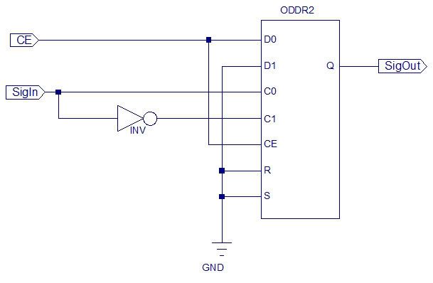
This is the Verilog Coding:
Now what do to about the 8-bit wide DataBus? Will each line have to go through an ODDR2? There are no bus-wide DDR2 FF's.
The Reset line is behaving correctly now (unsure what the deal is with the 800x480 latching the reset low, still awaiting its return), and I am seeing active signals on all the lines to the TFT. The TFT is behaving strangely, so I will need to concentrate on proper off-chip clock forwarding techniques.
These are the signals I need to bring out to the TFT:
A0, D0-D7, O2, WEn, TFTCSn, RESn.
A0 from CPU core selects 0=DCOM (TFT Command Reg) 1=DDAT (TFT Data Reg).
D0-D7 from CPU core. Lower 8 bits of Data Bus.
O2 from Spartan 6 DCM. Main 20MHz Clock signal out (clkfx) from 100MHz in DCM.
WEn. R/W to TFT. What has worked with the Spartan 3 is an inverted WE signal AND'd with O2...
TFTCSn is address decoded for active low $FFFF0010-$FFFF0011.
RESn is active low from POR DS1818. Inverted for CPU core RES.
So if I understand correctly, all signals must be output through a FF present on an IOB. For the Spartan 6 family these FF's are available as DDR types, which allows a signal to be clocked without dividing it's speed in half.
So schematicwise, I have something that looks like below. The inverter is local and hopefully will not create a delay problem, as I think the proper way to do it for strictest timing is to use the clkfx180 in conjuction with the clkfx from the DCM. (clkfx is the 20MHz used for the internal O2 clock). How would I go about hooking my signals up to this?
This is the Verilog Coding:
Code: Select all
module ClkOutFF(CE,
                SigIn,
                SigOut);

    input CE;
    input SigIn;
   output SigOut;

   wire XLXN_2;
   wire XLXN_7;

   ODDR2 #( .INIT(1'b0), .SRTYPE("SYNC"), .DDR_ALIGNMENT("NONE") ) XLXI_1
         (.CE(CE),
                 .C0(SigIn),
                 .C1(XLXN_2),
                 .D0(CE),
                 .D1(XLXN_7),
                 .R(XLXN_7),
                 .S(XLXN_7),
                 .Q(SigOut));
   INV  XLXI_2 (.I(SigIn),
               .O(XLXN_2));
   GND  XLXI_3 (.G(XLXN_7));
endmodule
Unless you're bringing out the clock itself, you should use regular FFs. This produces a valid signal on the output pad at the rising clock edge. Using DDRFF don't really give you an advantage. The advantage that the data is valid sooner is negated by the fact that this will shorten the timing budget inside the device, which will force you to use a lower clock.
-
ElEctric_EyE
- Posts: 3260
- Joined: 02 Mar 2009
- Location: OH, USA
Arlet wrote:
Unless you're bringing out the clock itself, you should use regular FFs...
I'm currently working now on running a successful ISim. Will have to go back to the original 65Org16.b Core before your recent updates. I may have messed up adding those updates from your postings on GitHub...
ElEctric_EyE wrote:
So you're saying use a DDR FF for the O2Out Clock and regular FF's for all the other signals?