Hi!
I’ve just started designing a new board, or more accurately, reverse-engineering it based on sparse information and a touch of sleep-deprived inspiration. To keep things manageable, I’m breaking the project into multiple subboards in KiCad. I’m starting with the power circuit (since that’s the easy one), then moving on to reset, CPU, ROM, RAM, address decoding, and eventually video (though let’s not get ahead of ourselves). Each subsystem will be on a separate board for easier debugging.
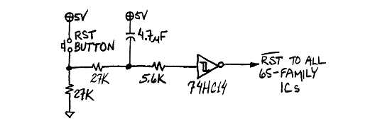
Right now, I’m working on the RESET circuit. Here’s what I have so far: (image attatched)
I’d love to get some feedback—does this circuit look solid? Any potential improvements or optimizations you’d suggest?
Thanks in advance for any input!
Is this a valid reset circuit
-
GARTHWILSON

- Forum Moderator
- Posts: 8773
- Joined: 30 Aug 2002
- Location: Southern California
- Contact:
Re: Is this a valid reset circuit
Welcome to 6502 land.
I have not used the 555 (or 556, which is two 555's in one IC) except in school 45 years ago, and I never really got familiar with it, preferring instead to do those functions with Schmitt-trigger gates or with comparators like the LM339 or LM393 (same thing, just 4 versus 2 comparators in one IC). I do have the SYM-1's reset circuit on the reset-circuit requirements page of the 6502 primer at http://wilsonminesco.com/6502primer/RSTreqs.html, which appears to be nearly identical to what you have (plus the reset pushbutton), except that it's for the 8-pin 555 rather than the 14-pin 556. I seem to remember WDC used to recommend a rise time on the reset line that the 555 couldn't meet, and even the 74LS06 with a 1K pull-up resistor on the output couldn't meet either, being too slow; but if they did make that recommendation, they seem to have dropped it since then. Some manufacturers had Schmitt-trigger RST\ inputs; but I never got a definitive list of which ones. The reset page linked above will show other ways to do it. I do recommend going through the entire 6502 primer though, in order, as it was written to answer a lot of questions and problems that kept coming up on the forum, and the pages kind of build upon previous pages' information to some extent. The last page is a "circuit potpourri," and starts out with a basic whole-computer schematic, and shows using a single IC for address-decoding logic and the reset circuit as well; IOW, you'll get away with fewer parts if you don't try to make lots of separate boards.
I have not used the 555 (or 556, which is two 555's in one IC) except in school 45 years ago, and I never really got familiar with it, preferring instead to do those functions with Schmitt-trigger gates or with comparators like the LM339 or LM393 (same thing, just 4 versus 2 comparators in one IC). I do have the SYM-1's reset circuit on the reset-circuit requirements page of the 6502 primer at http://wilsonminesco.com/6502primer/RSTreqs.html, which appears to be nearly identical to what you have (plus the reset pushbutton), except that it's for the 8-pin 555 rather than the 14-pin 556. I seem to remember WDC used to recommend a rise time on the reset line that the 555 couldn't meet, and even the 74LS06 with a 1K pull-up resistor on the output couldn't meet either, being too slow; but if they did make that recommendation, they seem to have dropped it since then. Some manufacturers had Schmitt-trigger RST\ inputs; but I never got a definitive list of which ones. The reset page linked above will show other ways to do it. I do recommend going through the entire 6502 primer though, in order, as it was written to answer a lot of questions and problems that kept coming up on the forum, and the pages kind of build upon previous pages' information to some extent. The last page is a "circuit potpourri," and starts out with a basic whole-computer schematic, and shows using a single IC for address-decoding logic and the reset circuit as well; IOW, you'll get away with fewer parts if you don't try to make lots of separate boards.
http://WilsonMinesCo.com/ lots of 6502 resources
The "second front page" is http://wilsonminesco.com/links.html .
What's an additional VIA among friends, anyhow?
The "second front page" is http://wilsonminesco.com/links.html .
What's an additional VIA among friends, anyhow?
-
BigDumbDinosaur

- Posts: 9425
- Joined: 28 May 2009
- Location: Midwestern USA (JB Pritzker’s dystopia)
- Contact:
Re: Is this a valid reset circuit
fan3000 wrote:
I’ve just started designing a new board...Right now, I’m working on the RESET circuit. Here’s what I have so far: (image attatched)
I use the Maxim DS1813, which is one part in a TO-92 package. The DS1813 is one of a number of similar devices that does what your circuit does in much less space.
An alternative if you want to “roll your own” is either this circuit or this one, both from Garth’s website. I’ve used the latter one to trigger the MPU’s NMIB input with a “panic button” that regains control if a programming error puts the MPU into an inescapable loop.
- Attachments
-
- reset_controller_ds1813.pdf
- Maxim DS1813 Reset Controller
- (206.15 KiB) Downloaded 99 times
x86? We ain't got no x86. We don't NEED no stinking x86!

Re: Is this a valid reset circuit
It may be valid but it's somewhat complex. Those little DS1813 and variants are a one-chip solution.
Or, at the other end of the scale, what I'm using on my retro 6507 system is nothing more that a 0.1µF capacitor and 10K resistor - is it valid? Who knows, but it's the same as was used on 30 million Atari 2600s. It works for me when the power supply has a fast startup.
-Gordon
Or, at the other end of the scale, what I'm using on my retro 6507 system is nothing more that a 0.1µF capacitor and 10K resistor - is it valid? Who knows, but it's the same as was used on 30 million Atari 2600s. It works for me when the power supply has a fast startup.
-Gordon
--
Gordon Henderson.
See my Ruby 6502 and 65816 SBC projects here: https://projects.drogon.net/ruby/
Gordon Henderson.
See my Ruby 6502 and 65816 SBC projects here: https://projects.drogon.net/ruby/

Re: Is this a valid reset circuit
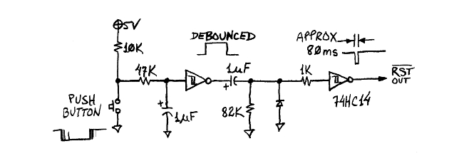
Pretty sure you can do this with a basic RC circuit, the 555 gives you a voltage comparator that can help, but you could use a Schmitt trigger to get the same effect:
This requires quite a number less support components than doing it with a 555 (556).
The basic idea is to hold the voltage low while the cap is charging. Changing the values of the resistor and cap will give different timings needed for a reset. The diode allows the cap to quickly discharge when the circuit is switched off.
Digi-Key has a calculator for getting the timing right:
https://www.digikey.com/en/resources/co ... e-constant
That being said I think the DS1813 is a good choice, as it's simple to setup and tailored to this exact need. The DS1511 (real time clock) basically has a similar function built into it, as I imagine several of the various RTCs have them as well.
There are of course alternatives to the DS1813 made by other companies that might have better price points if you need.
Re: Is this a valid reset circuit
GARTHWILSON wrote:
Welcome to 6502 land.
Some manufacturers had Schmitt-trigger RST\ inputs; but I never got a definitive list of which ones. The reset page linked above will show other ways to do it. I do recommend going through the entire 6502 primer though, in order, as it was written to answer a lot of questions and problems that kept coming up on the forum, and the pages kind of build upon previous pages' information to some extent. The last page is a "circuit potpourri," and starts out with a basic whole-computer schematic, and shows using a single IC for address-decoding logic and the reset circuit as well; IOW, you'll get away with fewer parts if you don't try to make lots of separate boards.
Some manufacturers had Schmitt-trigger RST\ inputs; but I never got a definitive list of which ones. The reset page linked above will show other ways to do it. I do recommend going through the entire 6502 primer though, in order, as it was written to answer a lot of questions and problems that kept coming up on the forum, and the pages kind of build upon previous pages' information to some extent. The last page is a "circuit potpourri," and starts out with a basic whole-computer schematic, and shows using a single IC for address-decoding logic and the reset circuit as well; IOW, you'll get away with fewer parts if you don't try to make lots of separate boards.
drogon wrote:
Or, at the other end of the scale, what I'm using on my retro 6507 system is nothing more that a 0.1µF capacitor and 10K resistor - is it valid? Who knows, but it's the same as was used on 30 million Atari 2600s. It works for me when the power supply has a fast startup.
-Gordon
-Gordon
I am going to look for the 2600 schematic and go from there, or going by Garth's solutions. Going to keep it up to date on this post.
Re: Is this a valid reset circuit
fan3000 wrote:
This actually seems a very valid, very simple solution, but, I live in a tropical, hot, humid place where you can't fully trust RC networks, casually, I have a 2600 clone(good ole Rambo TV Game), that only resets correctly like half the time(don´t know if they copied the original schematic or if they did something on their own for the reset).
I am going to look for the 2600 schematic and go from there, or going by Garth's solutions. Going to keep it up to date on this post.
I am going to look for the 2600 schematic and go from there, or going by Garth's solutions. Going to keep it up to date on this post.
-
BigDumbDinosaur
- Posts: 9425
- Joined: 28 May 2009
- Location: Midwestern USA (JB Pritzker’s dystopia)
- Contact:
Re: Is this a valid reset circuit
Yuri wrote:
The DS1511 (real time clock) basically has a similar function built into it, as I imagine several of the various RTCs have them as well.
No sir. The reset output in the DS1511 doesn’t respond to being grounded the way the DS1813 does. Reset in the DS1511 is primarily intended to be used with the watchdog timer in a supervisory mode. Typically, the watchdog is programmed to run at a relatively slow rate and to assert reset when it times out. As part of its operation, the MPU periodically reads the watchdog to restart it and prevent timing out. If the MPU goes belly-up, the watchdog will eventually time out and force a reset to restart operation.
x86? We ain't got no x86. We don't NEED no stinking x86!
Re: Is this a valid reset circuit
BigDumbDinosaur wrote:
Yuri wrote:
The DS1511 (real time clock) basically has a similar function built into it, as I imagine several of the various RTCs have them as well.
No sir. The reset output in the DS1511 doesn’t respond to being grounded the way the DS1813 does. Reset in the DS1511 is primarily intended to be used with the watchdog timer in a supervisory mode. Typically, the watchdog is programmed to run at a relatively slow rate and to assert reset when it times out. As part of its operation, the MPU periodically reads the watchdog to restart it and prevent timing out. If the MPU goes belly-up, the watchdog will eventually time out and force a reset to restart operation.
And yes, you can tie a watchdog timer to it, but it also serves as a power on reset circuit according to the datasheet:
Quote:
POWER-ON RESET
A temperature-compensated comparator circuit monitors the level of VCC . When VCC falls to the power-fail trip point,
the #RST signal (open drain) is pulled low. When VCC returns to nominal levels, the #RST signal continues to be
pulled low for a period of tREC . The power-on reset function is independent of the RTC oscillator and therefore
operational whether or not the oscillator is enabled.
-
BigDumbDinosaur
- Posts: 9425
- Joined: 28 May 2009
- Location: Midwestern USA (JB Pritzker’s dystopia)
- Contact:
Re: Is this a valid reset circuit
Yuri wrote:
BigDumbDinosaur wrote:
Yuri wrote:
The DS1511 (real time clock) basically has a similar function built into it, as I imagine several of the various RTCs have them as well.
No sir. The reset output in the DS1511 doesn’t respond to being grounded the way the DS1813 does. Reset in the DS1511 is primarily intended to be used with the watchdog timer in a supervisory mode. Typically, the watchdog is programmed to run at a relatively slow rate and to assert reset when it times out. As part of its operation, the MPU periodically reads the watchdog to restart it and prevent timing out. If the MPU goes belly-up, the watchdog will eventually time out and force a reset to restart operation.
And yes, you can tie a watchdog timer to it, but it also serves as a power on reset circuit according to the datasheet:
Quote:
POWER-ON RESET
A temperature-compensated comparator circuit monitors the level of VCC . When VCC falls to the power-fail trip point,
the #RST signal (open drain) is pulled low. When VCC returns to nominal levels, the #RST signal continues to be
pulled low for a period of tREC . The power-on reset function is independent of the RTC oscillator and therefore
operational whether or not the oscillator is enabled.
A temperature-compensated comparator circuit monitors the level of VCC . When VCC falls to the power-fail trip point,
the #RST signal (open drain) is pulled low. When VCC returns to nominal levels, the #RST signal continues to be
pulled low for a period of tREC . The power-on reset function is independent of the RTC oscillator and therefore
operational whether or not the oscillator is enabled.
x86? We ain't got no x86. We don't NEED no stinking x86!

Re: Is this a valid reset circuit
The DS1813 is the simplest way to get a proper reset. But they tend to be pricey (~$5) if bought from the big name houses.
The MCP100 is a much cheaper option (~$0.50) and if you need a reset button, just use a NC push button switch wired between it and Vcc.
The MCP100 is a much cheaper option (~$0.50) and if you need a reset button, just use a NC push button switch wired between it and Vcc.
Bill
-
richardc64

- Posts: 58
- Joined: 08 Jun 2013
- Contact:
Re: Is this a valid reset circuit
With different R&C values 555 + 74_06 are the reset circuit for VIC20, C64 and C128. The 74_06 open collector can be shorted to Gnd for a manual reset, but for my VIC and C64 I put a push button to Gnd at the tr pin to get consistent duration reset regardless of how long the button is pressed.
We all have our quirks, I'm sure: I once worked with a guy who wouldn't design with the 556 because he didn't have its pinout memorized, like he did for the 555
We all have our quirks, I'm sure: I once worked with a guy who wouldn't design with the 556 because he didn't have its pinout memorized, like he did for the 555
"I am endeavoring, ma'am, to create a mnemonic memory circuit... using stone knives and bearskins." -- Spock to Edith Keeler