6502.org Forum  Projects  Code  Documents  Tools  Forum
It is currently Thu Nov 21, 2024 11:03 pm

All times are UTC


Post new topic Reply to topic  [ 111 posts ]  Go to page Previous  1 ... 3, 4, 5, 6, 7, 8  Next
Author Message
PostPosted: Fri Aug 18, 2023 7:02 pm 
Offline

Joined: Fri Mar 18, 2022 6:33 pm
Posts: 491
Hi George,

Thanks for explaining. I like the look of those PCBs; neat design!

_________________
"The key is not to let the hardware sense any fear." - Radical Brad


Top
 Profile  
Reply with quote  
PostPosted: Fri Aug 18, 2023 8:30 pm 
Offline

Joined: Sun May 13, 2018 5:49 pm
Posts: 255
gfoot wrote:
I wasn't sure what to expect from the card edge connections, but they came out well. Crucially, they do fit into the sockets! I'm aware that the tin will get scratched off and connection quality will suffer, but interested to see how much abuse they take before that happens.

Here is AMP/TE's technical report on tin plating in contacts - it's only 10 pages and worth reading. I'm uploading it here as it seems to have disappeared off their website when they renamed/rebranded to TE.
Attachment:
File comment: Guidelines for tin plated contacts
tin_commandments.pdf [36.47 KiB]
Downloaded 58 times

Your plating is likely HASL, rather than straight tin (unless you specifically asked for tin). That's not a surface treatment that anyone would normally recommend for connector use, but it's likely to work fine for a period of time (probably measured in months) before it starts to give you issues. Your circuitry is low power and can likely handle some contact resistance with no trouble, so that will give you more time than if it was a high-power circuit.

If you have dielectric grease or contact cleaner that leaves a dielectric oil film behind (will advertise that it protects after cleaning), it will last longer if you lubricate the connection surface (after soldering your parts on) before mating it because it protects the surface from oxygen in the air.

If/when it starts to behave in a flaky manner, the standard practice of un-plugging and re-seating the card will likely fix it for another while. You can even blow on the connector, if you are of a certain age (8-bit Nintendo reference), but it's the wiping action of the contact that's actually pushing off the oxides and fixing the problem.


Top
 Profile  
Reply with quote  
PostPosted: Fri Aug 18, 2023 9:34 pm 
Offline

Joined: Fri Jul 09, 2021 10:12 pm
Posts: 741
SamCoVT wrote:
Here is AMP/TE's technical report on tin plating in contacts - it's only 10 pages and worth reading. I'm uploading it here as it seems to have disappeared off their website when they renamed/rebranded to TE.
Attachment:
tin_commandments.pdf

Your plating is likely HASL, rather than straight tin (unless you specifically asked for tin).

Yes indeed, sorry I used the word casually - I didn't know you could actually have tin :)

Thanks for all the information, that is very interesting. There were some plug-in modules for the BBC Micro that worked this way, and were notorious for this problem, so I was expecting it. In practice I'm expecting to iterate on the child boards quite a bit over time, so they don't need to last long; and depending where this goes, if it's a design I keep using then I can get some made with gold fingers instead. I'd like to get the design right first though!


Top
 Profile  
Reply with quote  
PostPosted: Sat Aug 19, 2023 4:46 am 
Offline

Joined: Fri Dec 21, 2018 1:05 am
Posts: 1117
Location: Albuquerque NM USA
I’ve designed several boards for Apple IIe with HASL contact fingers. They do work reasonably well. You can also clean contacts with eraser but I’ve not found it to be necessary for short term proof of concept testings. For long term reliability, the deliverable products have gold fingers.
Bill


Top
 Profile  
Reply with quote  
PostPosted: Sat Aug 19, 2023 7:11 am 
Offline
User avatar

Joined: Fri Aug 30, 2002 1:09 am
Posts: 8543
Location: Southern California
What I've done with tinned fingers that get a lot of plugging and unplugging from a board-edge connector is that after they get a lot of cycles, I just go over them with the soldering iron again, re-tinning, but letting the excess come off on the iron, so a good, new film of solder is left.  I think they can last indefinitely that way, as long as you don't let the copper underneath de-laminate from the PCB material.

_________________
http://WilsonMinesCo.com/ lots of 6502 resources
The "second front page" is http://wilsonminesco.com/links.html .
What's an additional VIA among friends, anyhow?


Top
 Profile  
Reply with quote  
PostPosted: Sat Aug 19, 2023 6:48 pm 
Offline

Joined: Fri Jul 09, 2021 10:12 pm
Posts: 741
This is coming together - just the CPU board to go. My wife helped with the soldering. The empty sockets are for ROM, a PLD, and the I/O clock oscillator as I'm not sure what speed to go with yet.


Attachments:
20230819_192008.jpg
20230819_192008.jpg [ 2.93 MiB | Viewed 21327 times ]
Top
 Profile  
Reply with quote  
PostPosted: Sun Aug 20, 2023 12:38 am 
Offline

Joined: Fri Jul 09, 2021 10:12 pm
Posts: 741
The CPU board is soldered as well now, but somehow I've managed to make a nasty error with the card edge connector - all its pins are on the opposite side of the board to where they should be! It seems to only affect the CPU board - the VIA board's pins seem to be fine. In the picture above, the VIA board when mounted correctly has its "front" side facing to the right, and the connector's even pins are on that side of the board; but I've somehow got the edge connector footprint flipped on the CPU board, so that when I mount it with pin 1 at the bottom as I intended, the front side of the board - with even-numbered pins - is to the left rather than to the right, while the receptacle footprint on the main board is consistent, expecting even pins on the right.

Unless anybody has any better ideas, I think I'm going to have to desolder the CPU slot connector and put it on the back of the main board instead for now, so that the contacts are on the correct side of it. It's going to be tricky to desolder it, and after remounting it the whole thing will be a bit of an awkward shape physically, but I expect I will make other variants of the CPU board in future (e.g. the 64K RAM version) and can fix the issue properly for those, and then I'll have to move the connector back to the front side of the main board again. I don't think I'll get another run of the CPU boards done just to fix this issue though, it's not worth it given I have a workaround.


Top
 Profile  
Reply with quote  
PostPosted: Sun Aug 20, 2023 4:58 am 
Offline

Joined: Mon Jan 19, 2004 12:49 pm
Posts: 983
Location: Potsdam, DE
Damn, I think we've all fallen into that hole at some time.

The only real solution is to redraw the processor PCB but you may be able to build an adaptor card to fit the socket and with a plug mounted to suit the processor. Still needs a PCB building - though you could perhaps use veroboard or similar? - but at least it gets everything on the right side of the backplane.

Neil


Top
 Profile  
Reply with quote  
PostPosted: Sun Aug 20, 2023 5:12 am 
Offline

Joined: Fri Dec 21, 2018 1:05 am
Posts: 1117
Location: Albuquerque NM USA
You have 4 slots; so you can sacrifice two slots and solder one side of the connector to one slot and the other side of the connector to the next slot. Most likely you’ll need to extend the connector’s pins to bridge the space between slots.
Bill


Top
 Profile  
Reply with quote  
PostPosted: Sun Aug 20, 2023 12:52 pm 
Offline

Joined: Fri Jul 09, 2021 10:12 pm
Posts: 741
barnacle wrote:
Damn, I think we've all fallen into that hole at some time.

The only real solution is to redraw the processor PCB but you may be able to build an adaptor card to fit the socket and with a plug mounted to suit the processor. Still needs a PCB building - though you could perhaps use veroboard or similar? - but at least it gets everything on the right side of the backplane.

It's relatively easy to change the processor PCB to fix the issue, as the pads are just on the wrong sides of the board. I could even just swap the layers, without any layout changes! I think that's actually how this happened - I'd probably planned to do that but not followed through with it. My memory is very poor but I think I originally had pin 1 of the CPU connector at the opposite end, but wanted to relabel it so that its pin 1 was at the same end as the one for the I/O slots. I must have missed a step while doing that, and not checked thoroughly enough afterwards.

Veroboard is an interesting option, but I only have single-sided veroboard (can you get double-sided ones?) so it wouldn't work for a double-sided edge connector.

plasmo wrote:
You have 4 slots; so you can sacrifice two slots and solder one side of the connector to one slot and the other side of the connector to the next slot. Most likely you’ll need to extend the connector’s pins to bridge the space between slots.

Those slots aren't all the same - the I/O slots have fewer pins and only carry the signals required by a 6522, plus a few extras.

Desoldering went well for about half of the pins, but my desoldering station has stopped sucking properly - I was trying to keep it clean as I went along, but I must have done something wrong. I suspect the nozzle is blocked fairly deep inside, but I need to take the gun apart to see what's really going on.

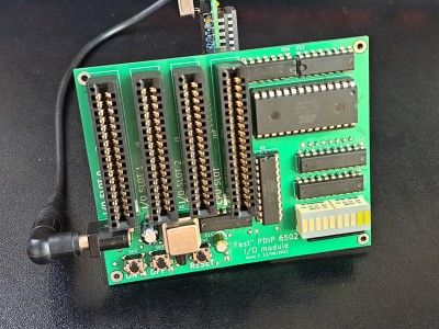
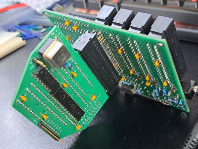
I am considering a plan B of soldering an additional connector to the reverse side of the board, onto the pins of the existing connector, so that I don't need to remove it, with the benefit that I also don't need to move it back to the front of the board when I get a fixed CPU board made. It will be fragile though in the meantime if I do this, and I do want to figure out what's wrong with my desoldering gun as it's such a useful tool.

Edit: I went for Plan B, soldering a second CPU connector on the back, and while it's very messy after ask the desoldering and resoldering, it does work - here it's running a memory stress test at 32.768MHz:

Attachment:
20230820_155205.jpg
20230820_155205.jpg [ 4.12 MiB | Viewed 21261 times ]

Attachment:
20230820_155247.jpg
20230820_155247.jpg [ 4.26 MiB | Viewed 21261 times ]


The next faster oscillator I have is 40MHz but that doesn't run. I think phase 1 is too short because it doesn't even run from ROM (which is easiest as phase 2 is very long in that case). There are some experiments to do around that I think - it could be my circuit's limitation, or the CPU's. It's possible that with an unbalanced duty cycle it would work.

I haven't run the Dormann tests yet as I can't easily hook up my serial output circuit, I hadn't thought of it. I may run them without output though and use the logic analyser and decoder to see the results or debug them.


Top
 Profile  
Reply with quote  
PostPosted: Mon Aug 21, 2023 6:50 pm 
Offline

Joined: Fri Jul 09, 2021 10:12 pm
Posts: 741
I've rigged my PCB prototype to run both Dormann suites one after the other indefinitely, halting on any failure - they just about fitted in the 32K ROM together. Failure - or rather progress - is only indicated through the eight debug port LEDs which pulse every few seconds while the tests are running healthily. It's happily been doing that for an hour or two, running at 32.768MHz.

I don't have any useful output set up for the PCB prototype, as it's not as easy to bodge things in that weren't planned for as it is with breadboards. I might make a generic I/O card that simply breaks out the I/O bus lines, maybe with a little extra useful logic on board, so that I can more easily plug in experimental hardware in future.

Otherwise, I need to use test clips to attach to IC pins, and I can't for the life of me work out how to solder wires into the bare sheet metal of the ones I have! Perhaps it needs hot air to heat the metal up enough that solder will melt on it, but I fear the plastic would then also melt. I gave up and ordered some with wires already attached.

Those are needed for the logic analyser to work, because the data bus breakout I put on my CPU board is on the far side of the data bus transceiver, and the LA doesn't get good enough samples from there - it works most of the time but gets the odd thing wrong.

I have also soldered up one of the little DS1086 programmable oscillator adaptor boards:

Attachment:
20230821_191714.jpg
20230821_191714.jpg [ 570.95 KiB | Viewed 21232 times ]

Attachment:
20230821_191729.jpg
20230821_191729.jpg [ 562.51 KiB | Viewed 21232 times ]


Those capacitors were awkward. Hot air blew them away and I didn't have a good way to hold them in place, so I did this with a soldering iron. It is not great but it is not shorted and there is continuity where there should be, so hopefully it's fine.

The pin header is for SPI programing of the oscillator. It will allow me to try rates between the current 32MHz and 40MHz where it stops working. I need to dig out something to program it with though!

Finally, I experimented with faster serial at the weekend, and had it working at about 940000 baud. It was using a 16MHz I/O clock divided by 17 as the bit clock. That's just silly though, I'm not going to keep using it at that pace and I've reconfigured it to a slower speed again.


Top
 Profile  
Reply with quote  
PostPosted: Mon Aug 21, 2023 7:19 pm 
Offline

Joined: Fri Dec 21, 2018 1:05 am
Posts: 1117
Location: Albuquerque NM USA
Glad to see your hardware running to 32.7mhz. I suspect you can run it higher to 36-40Mhz. If failure is encountered, you can squeeze a MHz or two by raising the 5V voltage.
Bill


Top
 Profile  
Reply with quote  
PostPosted: Mon Aug 21, 2023 7:37 pm 
Offline

Joined: Fri Jul 09, 2021 10:12 pm
Posts: 741
plasmo wrote:
Glad to see your hardware running to 32.7mhz. I suspect you can run it higher to 36-40Mhz. If failure is encountered, you can squeeze a MHz or two by raising the 5V voltage.
Bill

Ah interesting! Someone else suggested freezer spray! I don't know whether these things prefer being cold though.


Top
 Profile  
Reply with quote  
PostPosted: Mon Aug 21, 2023 10:16 pm 
Offline

Joined: Fri Dec 21, 2018 1:05 am
Posts: 1117
Location: Albuquerque NM USA
CMOS devices will speed up when cold so you can raise voltage AND freeze it to gain more speed. I do worry about condensation forming when cold. You can put it in plastic bag, suck out the air, put it in freezer for an hour and power up while in the bag.
Bill


Top
 Profile  
Reply with quote  
PostPosted: Tue Aug 22, 2023 5:04 am 
Offline

Joined: Mon Jan 19, 2004 12:49 pm
Posts: 983
Location: Potsdam, DE
Added cold is good, but those pesky PN junctions tend to get a bit confused once you're down below a couple of hundred K. Practical concerns are bandgap reference voltage changes and decreased noise immunity, but you should be fine down to about -40C.

Condensation tends to occur when something warm is brought into a warmer wetter atmosphere, so starting with a dry board - perhaps encapsulated, or including a drying agent - is probably sufficient.

Neil


Top
 Profile  
Reply with quote  
Display posts from previous:  Sort by  
Post new topic Reply to topic  [ 111 posts ]  Go to page Previous  1 ... 3, 4, 5, 6, 7, 8  Next

All times are UTC


Who is online

Users browsing this forum: No registered users and 36 guests


You cannot post new topics in this forum
You cannot reply to topics in this forum
You cannot edit your posts in this forum
You cannot delete your posts in this forum
You cannot post attachments in this forum

Search for:
Jump to:  
cron