6502.org Forum  Projects  Code  Documents  Tools  Forum
It is currently Fri Apr 19, 2024 3:22 am

All times are UTC


Post new topic Reply to topic  [ 6 posts ] 
Author Message
PostPosted: Mon Nov 20, 2006 5:49 am 
Offline

Joined: Wed Nov 24, 2004 6:24 pm
Posts: 26
Location: Adelaide
Hi

I found myself a SYM-1 and its manual in my TAFE college's soldering lab, having been attacked by students for soldering practice. It was missing the keypad, the CPU was dead and the ROM's had been incorrectly replaced with 2732's. I fixed these and it works fine now :)

Now to make it do something fun.

In Sym-Physis issue 7 there are details for attaching an AY-3-8912 and in the article it says 'Hardware Requirements: 6K RAM, BASIC, Keyboard terminal with at least 40 characters per line and at least 24 lines, AY-3-8912 wired per Table 1'

No Table 1 in sight :(

Could someone provide me with the schematic? I'd prefer to keep to some sort of set standard rather than making my own so other programs which use the chip (there's a game there) can work without modification.

Thanks.

_________________
Check out my 8080 project: http://kaput.homeunix.org


Top
 Profile  
Reply with quote  
 Post subject:
PostPosted: Mon Nov 20, 2006 5:39 pm 
Offline

Joined: Fri Jun 27, 2003 8:12 am
Posts: 618
Location: Meadowbrook
If it helps, look around for the Mockingboard schematic and code for the Apple 2. PLus a whole bunch of older arcadew games used that sound and port chip.

_________________
"My biggest dream in life? Building black plywood Habitrails"


Top
 Profile  
Reply with quote  
 Post subject:
PostPosted: Wed Nov 22, 2006 2:03 pm 
Offline

Joined: Tue Mar 09, 2004 3:43 pm
Posts: 44
Location: Bristol, UK
Well done for rescuing and fixing up that SYM-1! I have one here, too, that was used in education -- but wasn't used for soldering practice.

As for the AY-3-8912, there's an AY sound chip home page here:

http://bulba.at.kz/main_e.htm

maybe there's a circuit on that site?

John Honniball


Top
 Profile  
Reply with quote  
 Post subject:
PostPosted: Thu Nov 23, 2006 3:41 am 
Offline

Joined: Wed Nov 24, 2004 6:24 pm
Posts: 26
Location: Adelaide
I've found this. http://www.simandl.cz/stranky/zxs/obrazky/ay_stereo.jpg . I used a similar schematic for my 8080 project (this one's for the Z80).

Looks like I'll have to reverse engineer the BASIC listings, now that I've got BASIC going, to figure out what pin goes where.

If I get it going I'll post the schematic for it.

EDIT: Bah I'm an idiot. There it is... I was looking for a schematic, not a table. It doesn't use any logic at all, it's all done in software. The AY had a very odd pinout for the equally odd CPU it was designed to run on.

_________________
Check out my 8080 project: http://kaput.homeunix.org


Top
 Profile  
Reply with quote  
 Post subject:
PostPosted: Sat Nov 25, 2006 6:01 pm 
Offline

Joined: Wed Nov 24, 2004 6:24 pm
Posts: 26
Location: Adelaide
Got something going. I noticed some of the connections in the table were unnecessary so I've modified the schematic a little, but it remains software compatible with the software presented in Sym-physis.

http://kaput.homeunix.org/~thrashbarg/ay-3-8912.png

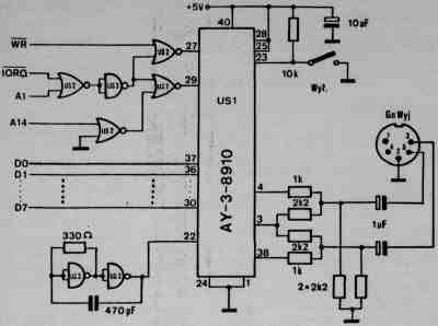
I've made the schematic for the AY-3-8912 which is a 28 pin version of the 8910 and I believe it's more common. Please say if It's not. They can be found in Amstrad CPC's and Spectrum's, if you're willing to sacrifice one. If you've got an 8910 or an 8913 please check the datasheet for the correct pinouts.

One thing I've left out is the clock. I'll leave that up to you. You can use the 1 or 2MHz clock from the 6502. Some datasheets for the AY have a frequency table for a 1.78975MHz clock, or half of the NTSC frequency.

The use of port B on the VIA is unnecessary, but changing it would require the software to be changed. They can easily be attached to CB1 and CB2 of the VIA if you want to keep port B free.

Here's some code, based around the demo in Sym-physis:
Code:
1 VIA=#####
10 GOSUB 1000
20 RE=0:DT=255
25 GOSUB 2000
30 RE=1:DT=0
35 GOSUB 2000
40 RE=7:DT=254
45 GOSUB 2000
50 RE=8:DT=15
55 GOSUB 2000
60 FOR A=1 TO 300:NEXT
70 RE=8:DT=0
75 GOSUB 2000
100 END
1000 POKE VIA+2,7:POKE VIA+3,255
1010 RETURN
2000 POKE VIA+1,RE
2010 POKE VIA,7
2020 POKE VIA,0
2030 POKE VIA+1,DT
2040 POKE VIA,6
2050 POKE VIA,0
2060 RETURN


Line 1 should be changed to set the base address of the VIA. 40960 for the application connector on the SYM-1.

Lines 1000-1010 initialize the VIA to write to the AY.
Lines 2000-2060 send data DT to register RE of the AY.

The code should make a short beep.

Of course if you wanted REAL sound you could always use a SID :)

_________________
Check out my 8080 project: http://kaput.homeunix.org


Top
 Profile  
Reply with quote  
 Post subject:
PostPosted: Sun Nov 26, 2006 2:49 pm 
Offline

Joined: Mon Mar 20, 2006 2:03 am
Posts: 24
Thrashbarg wrote:
Of course if you wanted REAL sound you could always use a SID :)


Anyone know of a source for those (besides ripping apart 64s)?

I helped build a time/temp clock for a bank in Philadelphia once, they wanted Westminster chimes so we used a SID chip with the ring modulator bell sound, worked out real nice.


Top
 Profile  
Reply with quote  
Display posts from previous:  Sort by  
Post new topic Reply to topic  [ 6 posts ] 

All times are UTC


Who is online

Users browsing this forum: No registered users and 0 guests


You cannot post new topics in this forum
You cannot reply to topics in this forum
You cannot edit your posts in this forum
You cannot delete your posts in this forum
You cannot post attachments in this forum

Search for:
Jump to: