Page 1 of 2
Clock (and I guess other signals) waveforms
Posted: Thu Jun 23, 2022 7:27 am
by adrianhudson
I have a 1mhz can oscillator. On the bench (not in circuit) the square wave signal looks like image 1. If I extend the output pin with a 6 inch piece of wire, it looks like image2.
I'm sure the ringing (is that the correct term?) must matter. How do I clean this signal up?
Re: Clock (and I guess other signals) waveforms
Posted: Thu Jun 23, 2022 8:19 am
by GARTHWILSON
This part here might be concerning, as it's bouncing enough to change states again, long before the processor or something like a VIA would be ready for the next edge:
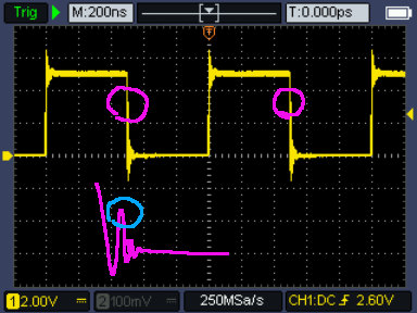
- bounce.jpg (52.39 KiB) Viewed 3566 times
(The purple squiggle blow is my guess at an expanded view of that ringing edge.) Can you post a photo of the board that produced this?
Re: Clock (and I guess other signals) waveforms
Posted: Thu Jun 23, 2022 10:11 am
by BigEd
It'd be worth zooming in to see if that really is happening. But if it is, it is indeed worth doing something about.
Slowing down the edges will help, as will having good ground return.
Note that what you see on a scope isn't what's happening - the scope has limited bandwidth, the probe has its own characteristics, and the ground path you put in place for the probe will also have a big effect. Make sure you've adjusted your probes correctly ("compensated" or "calibrated" them) and consider using the twirly spring tactic for grounding the probe.
https://electronics.stackexchange.com/q ... und-spring
Also, it will matter what the clock is driving - what kind of load. Your clock driver should be appropriately sized for the load, so the edges are adequately fast for correct operation but not as fast as possible.
You probably won't need to add resistors at the near end or the far end, but "terminating the line" is a term that you might come across.
Re: Clock (and I guess other signals) waveforms
Posted: Thu Jun 23, 2022 11:33 am
by CountChocula
One thing that might be helpful is to tell us why you’re asking. The ringing you see could just be an artifact of the way you’re measuring it (as Garth mentioned), and so it isn’t necessarily something worth worrying about unless it’s causing problems.
Re: Clock (and I guess other signals) waveforms
Posted: Thu Jun 23, 2022 1:45 pm
by drogon
One thing that might be helpful is to tell us why you’re asking. The ringing you see could just be an artifact of the way you’re measuring it (as Garth mentioned), and so it isn’t necessarily something worth worrying about unless it’s causing problems.
This too...
I keep telling myself that my 16Mhz '816 system works because I don't have the test kit to tell my why it shouldn't work...
Cheers,
-Gordon
Re: Clock (and I guess other signals) waveforms
Posted: Thu Jun 23, 2022 1:59 pm
by CountChocula
I keep telling myself that my 16Mhz '816 system works because I don't have the test kit to tell my why it shouldn't work...
Yes, big +1 to that… I spent a lot of time trying to measure things at the beginning, until a number of folks here helped me understand that it's not that important unless you have a problem. My projects started moving much faster once that sunk in

(Also, it was Ed who suggested that the problem might be artefacts… apologies for the mixup!)
Re: Clock (and I guess other signals) waveforms
Posted: Thu Jun 23, 2022 2:33 pm
by BigDumbDinosaur
I saw no mention of the presence or absence of a bypass capacitor at the VCC and ground pins of the oscillator. I also didn’t see anything describing the robustness of the VCC and ground connections. Also, how about loading? All of these are factors that will affect signal quality, or lack thereof.
As the others implied, you may be seeing a problem that doesn’t actually exist.
Re: Clock (and I guess other signals) waveforms
Posted: Thu Jun 23, 2022 2:54 pm
by adrianhudson
Oklay, thanks all for your thoughts!
Some answers:
...it's bouncing enough to change states again, long before the processor or something like a VIA would be ready for the next edge:
and
It'd be worth zooming in to see if that really is happening. But if it is, it is indeed worth doing something about.
Here is a zoomed in graph (Sorry, I pressed the wrong button on my scope and got an excel file - so I graphed it). Perhaps I am indeed worrying too much - it probably isn't bad enough to change states. Do you agree?
By the way, there is no board that produced this graph. The can is on the bench (okay, kitchen table!) with +5v, GND, and the scope probe attached - and I have checked the calibration of my probe.
One thing that might be helpful is to tell us why you’re asking. The ringing you see could just be an artifact of the way you’re measuring it (as Garth mentioned), and so it isn’t necessarily something worth worrying about unless it’s causing problems.
I ask because I have been having problems with the SBC that this oscillator is normally part of. (See:
viewtopic.php?f=4&t=2029). Before I take it all apart and start again I was casting around for other possible causes of the wierdness I am getting with interrupts. I decided to start a newbie thread as a) I am a newbie in this area (analogue electronics) and b) I thought it sufficiently off topic to start another thread.
-snip-
Slowing down the edges will help, as will having good ground return.
-snip-
Also, it will matter what the clock is driving - what kind of load. Your clock driver should be appropriately sized for the load, so the edges are adequately fast for correct operation but not as fast as possible.
You probably won't need to add resistors at the near end or the far end, but "terminating the line" is a term that you might come across.
BigEd, please could you explain in a bit more detail (remember - analogue electronics dummy here) what you mean.
"Slowing down the edges" How?
"What its driving". It isn't driving anything as per the graphs above - the can is powered and has a scope lead on the output - it normally drives a 65C02, 65C22 and 65C51.
"You probably won't need to add resistors..." I read an exchange between someone here and an expert (I forget the name) that went into series resistors but firstly, I didn't fully understand a lot of it and secondly, they didn't go into a lot of explanation. Could you explain how its done and why please.
Re: Clock (and I guess other signals) waveforms
Posted: Thu Jun 23, 2022 4:36 pm
by BigEd
(Sorry - I think you'd be better off looking into resources like electronics stackexchange, rather than have me write an essay. In my opinion, it's well worth the journey of trying to understand electronics, and you have some of the gear to help you. But you will need to do the work - you need to build a mental model and you need to have some terminology to hand. Good luck!)
Re: Clock (and I guess other signals) waveforms
Posted: Thu Jun 23, 2022 5:47 pm
by BigDumbDinosaur
(Sorry - I think you'd be better off looking into resources...)
I’ll second that. Digital circuitry design and implementation is not something readily explained in the space of some forum posts.
One quick note...in digital circuits, operating speed—the Ø2 clock in 65xx circuits—is tangentially related to stability issues. We’ve often said that you can get away with murder at 1 MHz, but the reality is that statement is more facetious than helpful. The rise and fall rates of devices’ outputs are more often to blame for instability than is the Ø2 rate. This is because an extremely fast signal transition, even one that only happens a few times per second, has frequency components that go into the hundreds of MHz. The WDC microprocessors fall into that category, as do 74AC, AHC and HC logic devices—most critically with 74AC. So while you might be able to get away with murder at 1 MHz, the odds aren’t in your favor if construction techniques are not up to snuff.
Re: Clock (and I guess other signals) waveforms
Posted: Thu Jun 23, 2022 6:01 pm
by CountChocula
Here is a zoomed in graph (Sorry, I pressed the wrong button on my scope and got an excel file - so I graphed it). Perhaps I am indeed worrying too much - it probably isn't bad enough to change states. Do you agree?
That looks reasonable to me—you should be okay (but again, what you see is probably not what's happening in circuit).
I ask because I have been having problems with the SBC that this oscillator is normally part of. (See:
viewtopic.php?f=4&t=2029). Before I take it all apart and start again I was casting around for other possible causes of the wierdness I am getting with interrupts. I decided to start a newbie thread as a) I am a newbie in this area (analogue electronics) and b) I thought it sufficiently off topic to start another thread.
I can't find your message in the thread you linked; mind double checking that you pasted the right URL?
BigEd, please could you explain in a bit more detail (remember - analogue electronics dummy here) what you mean.
"Slowing down the edges" How?
Fellow newbie here, so the following might be wrong—hopefully, someone can confirm or correct.
My understanding is what drives a lot of noise and ringing in digital signals is the rate at which a line switches from one state to another—that is, the slope of the transition edge—independent of the clock at which the circuit is running. This topic has been covered extensively in the forums, and so you can find a tonne of information just looking around (for example, that URL you posted above). You can slow the edge (that is, decrease the slew rate) by adding a resistor in series between the clock circuit and the load; however, you want to be careful not to violate the CPU's maxima. FWIW, in my very limited time playing around with the 6502, I've never had this problem even at much higher speeds, and I'd be surprised, based on what I've read, if this were the cause of the problem you're experiencing. Here's a
thread on StackExchange where this is explained.
"You probably won't need to add resistors..." I read an exchange between someone here and an expert (I forget the name) that went into series resistors but firstly, I didn't fully understand a lot of it and secondly, they didn't go into a lot of explanation. Could you explain how its done and why please.
I think this is a different kind of problem—termination of the line to prevent reflections. This is also been discussed many times; if you search the forum for “bus termination,” you should find what you're looking for.
The thing is, I think most of these answers are based on addressing the behaviour of the clock signal
in circuit, which is really not the condition you're testing under… so I suspect you may be going down a bit of a rabbit hole
I hope this helps (and is not too wrong). Cheers!
Re: Clock (and I guess other signals) waveforms
Posted: Thu Jun 23, 2022 8:59 pm
by adrianhudson
(Sorry - I think you'd be better off looking into resources like electronics stackexchange, rather than have me write an essay. In my opinion, it's well worth the journey of trying to understand electronics, and you have some of the gear to help you. But you will need to do the work - you need to build a mental model and you need to have some terminology to hand. Good luck!)
Well thanks for that
I really apologise. I wasn't aware there was a limit to the type of question allowed here. I thought this was a newbie forum where people trying to learn stuff came to ask questions. Sorry
Re: Clock (and I guess other signals) waveforms
Posted: Thu Jun 23, 2022 9:04 pm
by adrianhudson
Dear CountChocula,
Thank you very much for your kind reply. Very useful. I will search for the terms you mention. I posted an incorrect link the link I meant was
viewtopic.php?f=4&t=7204
Adrian
Re: Clock (and I guess other signals) waveforms
Posted: Thu Jun 23, 2022 11:26 pm
by BillO
It would be handy to see a picture of your test set-up.
The kind of "ringing" you are seeing on the clock transitions can be caused by a long scope lead ground and the lack of supply bypassing. You need to understand that there is a lot going on here that might not meet the eye. For instance, the can oscillator might only be a 1MHz frequency, but that is just the clock rate. The leading and trailing edges of the pulses rise and fall at a rate that could represent frequencies in the 100s of MHz range. Further, being able to switch that fast means there will be a considerable spike in current draw when the transitions occur. These will need some local energy store to satisfy. We refer to this as bypassing the supply and it's normally done with one or more small capacitors (~0.1uF). So, adding a bypass capacitor and shortening the ground lead on the scope wire (do you have a whisker ground lead?) will go a long way to cleaning up the signal.
I don't think Big Ed meant to curtail your asking questions, it just seems that there is quite a bit of the basics you don't understand. A forum like this in not a great place to learn electronics form the ground up. It can easily lead to a veritably endless series of questions as we try to answer one question you have with terms you may not be familiar with only leading to further questions. Which is exactly what happened here. There are a lot of on-line resources for leaning the basics All About Circuits, stackexchange etc..
Re: Clock (and I guess other signals) waveforms
Posted: Fri Jun 24, 2022 4:51 am
by BigDumbDinosaur
My understanding is what drives a lot of noise and ringing in digital signals is the rate at which a line switches from one state to another...
For instance, the can oscillator might only be a 1MHz frequency, but that is just the clock rate. The leading and trailing edges of the pulses rise and fall at a rate that could represent frequencies in the 100s of MHz range.
Funny how everyone is repeating what I earlier posted. 