Page 1 of 5
[Contest] TIM history
Posted: Thu Jan 16, 2020 1:10 am
by jds
(I’m travelling at the moment and am writing this on an iPad all from memory, so it’ll have to be quite brief, hopefully I’ve got everything right)
The 6530-004 is a 6532 part with the TIM monitor ROM preprogrammed. This was sold as a kitset with a sample schematic and was one of the first 6502 development systems (and probably the simplest ever made). The TIM monitor was written at MOS technology (on contract) and is one of the first pieces of 6502 software.
I’m going to base my design off the schematic that came with the TIM kit, and build up the example system. I will omit the current loop interface as that is not very useful now, but will include what they called the EIA interface, which is a very simple but standard serial port. I’ll try and get period accurate chips for everything, but can’t source a 6530-004 so will have to use the 6532 and EPROM. If I could figure out a way to hide a tiny ROM under the 6532 I’d like to do something like that, but it doesn’t look like there is anything that can fit. I even thought of getting one of those chip fakers that cause us so much grief to make me a 6530 out of a 6532 (in looks, not functionality). I plan on adding some 2114 RAM to bring the RAM up to 1k. The TIM schematic has a simple mechanism to allow remapping of the 6532 RAM into the vector areas so that the vectors are in RAM after startup. The reset is a manual button that you need to press after powering up.
I’ll add an expansion edge connector to the PCB to allow for more useful functionality. I’m thinking of implementing a EEPROM programmer expansion board as that is one of the things that everyone needs starting out. So in theory your could buy your preprogrammed TIM ROM and then you’d be able to make your own ROM’s from then on.
An important part of this project is documenting the TIM and it’s history (or pointing to existing information on the web). I’d also like to see if I could get Tiny BASIC running too. It’ll require more ROM and RAM but will easily fit in the 8k address space.
Re: [Contest] TIM history
Posted: Thu Jan 16, 2020 9:03 am
by BigEd
Sounds great!
Re: [Contest] TIM history
Posted: Thu Jan 16, 2020 9:14 am
by fhw72
I still have a few 6530-004 left:
And I guess you already know this site with Information about it:
http://retro.hansotten.nl/6502-sbc/tim-6530-004/
Re: [Contest] TIM history
Posted: Fri Jan 17, 2020 5:55 am
by jds
I still have a few 6530-004 left:
That’s probably most of the world’s remaining supply, and ceramic too. I’ve been trying to find some Rockwell branded ones but they are impossible to get.
Yes, some really good information there. The Rockwell manual is a great resource. My schematic is based off of that.
Re: [Contest] TIM history
Posted: Fri Jan 17, 2020 9:33 pm
by fhw72
Did Rockwell also produce 6530-004? I've got a few (ceramic) 6532 from Rockwell.... but no 6530
Re: [Contest] TIM history
Posted: Fri Jan 17, 2020 9:55 pm
by jds
Did Rockwell also produce 6530-004? I've got a few (ceramic) 6532 from Rockwell.... but no 6530
They did. Their TIM manual appears to be the best reference for TIM boards, but I think they moved on soon after to put a lot of effort into the AIM-65, which appears to be based on the KIM-1 type boards but went way further. There was quite a lot of software for the AIM-65 and you could get video and disk interfaces.
Re: [Contest] TIM history
Posted: Fri Jan 17, 2020 10:02 pm
by jds
My first bit of research has been into power supplies, based on the plan of building a period accurate power supply for the TIM board. I’m starting to realise how easy we have it now. My first path of investigation was to look at the Apple 1 power supply as it’s of the same period. The first thing that struck me was the giant capacitors. These seem really hard to get now and are very expensive. The next thing is the voltages, +12, -12, +5, and -5. There’s not a lot of need for all of these today, and our biggest issue is the transition to 3.3v. If I build the serial port as per the schematic I’ll need the +12 and -12. Mostly I think the -5 was used for older RAM chips. I won’t be going back that far so can eliminate that one, but it’s probably one of the easier ones to generate. Then I had a look for transformers, and they are getting hard to find and are expensive. They are heavy things so shipping is an issue (but not as bad as a CRT). So building a period accurate power supply is very simple from a technical sense, but the parts are getting hard to get.
Re: [Contest] TIM history
Posted: Fri Jan 17, 2020 11:06 pm
by Chromatix
Could you use a PC-type PSU for this? You'd need to find one that doesn't have a no-load shutdown, but it'll provide +12, +5 and -12 safely in a nice big metal box.
Re: [Contest] TIM history
Posted: Sat Jan 18, 2020 9:48 pm
by ElEctric_EyE
... in a nice big metal box.
Not so big. Even the oldest PC SMPS's.
A PC type power supply is a great suggestion. You just need to put a jumper between the green and black wires to bypass the no-load shutdown. Then it'll run as soon as you throw the switch.
Re: [Contest] TIM history
Posted: Mon Jan 20, 2020 3:40 am
by Chromatix
Well, it's a big metal box when you compare it to the average wall-wart, which is all you'd need to supply a single voltage these days.
Re: [Contest] TIM history
Posted: Mon Jan 20, 2020 11:07 pm
by ElEctric_EyE
Re: [Contest] TIM history
Posted: Mon Jan 20, 2020 11:29 pm
by GARTHWILSON
I haven't looked, but I think you could find an inexpensive wall wart or table-top triple power supply with +5V and ±12V. The ±12V (very non-critical, and doesn't even need to be regulated) is useful for a lot of things that might go on a computer board.
Every electronics hobbyist should have a triple bench power supply. I used to recommend the Global 1300 and 1310 which were inexpensive, but they've quit making it. Now they only have much bigger, more expensive ones with far more power than we need for these projects, so I need to find another one to recommend.
Re: [Contest] TIM history
Posted: Tue Jan 21, 2020 12:44 am
by cjs
My first bit of research has been into power supplies, based on the plan of building a period accurate power supply for the TIM board. I’m starting to realise how easy we have it now.... So building a period accurate power supply is very simple from a technical sense, but the parts are getting hard to get.
Yup. I had a similar idea for a PSU for my Commodore 64, having vague memories of my simple high-school power supplies built with just a transformer, diode bridge and perhaps a cap or two, and I too found out that transformers are pretty expensive and not entirely trivial to source these days. (Were they ever cheap? Or was I just used to stuff being expensive?)
So far nobody's given any suggestions that don't involve giving up period accuracy. If you are going to abandon that, certainly a modern PC power supply is workable, but you also need to remember that it's not unusual for these supplies to require a minimum load, as well as needing to have the internal switch shorted. And the smaller they are, the noisier the fan. Personally, I'd go with Garth's idea of just sourcing a smaller and quieter switching PSU. There are plenty out there that provide a half amp of -5V and -12V, 1-2 A of +12V, and 4 A or more of +5V. Examples from AliExpress include
this,
this and
this.
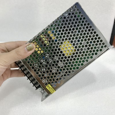
- sm-quad-psu.jpg (51.38 KiB) Viewed 3257 times
Wall warts can also work: for my C64 I ended up going with
two wall warts, one for the +5 VDC, (which is dead easy to find), and one for the 9 VAC (which also wasn't so hard, and the reason I couldn't just use my bench supply).
And yes, though not applicable to my particular C64 problem, now that I've had some experience I wish I'd spent a bit more and bought at least a two-channel bench supply. I live with an
adjustable wall-wartish thing when I need a second voltage and I can't take +5 from my USB power supply, but I wouldn't use that into something without its own regulator because it's pretty tricky to adjust accurately.
Re: [Contest] TIM history
Posted: Tue Jan 21, 2020 8:39 pm
by jds
So far nobody's given any suggestions that don't involve giving up period accuracy. If you are going to abandon that, certainly a modern PC power supply is workable, but you also need to remember that it's not unusual for these supplies to require a minimum load, as well as needing to have the internal switch shorted. And the smaller they are, the noisier the fan. Personally, I'd go with Garth's idea of just sourcing a smaller and quieter switching PSU. There are plenty out there that provide a half amp of -5V and -12V, 1-2 A of +12V, and 4 A or more of +5V. Examples from AliExpress include
this,
this and
this.
I think that is the conclusion I am coming to, that one of these switching power supplies is a good realistic choice, but is also a bit like the old metal box power supplies that the AIM-65 used, or even at a stretch it's similar to the Apple ][. I found a Mean Well unit that had +12 and -12 and I could regulate from there. I don't need -5 and the +-12 is only for the serial port. In a modern design you could do away with that too by going direct from 5V to USB. At the time it was up to the user to provide a power supply in most cases, the power supply not being a part of the system.
Thanks for the suggested units, I hadn't found most of those.
Feature creep is setting in again, but I am trying to resist. I've got this idea of adding a card edge connector for expansion, with a similar layout to the KIM-1, or AIM-65. There isn't a footprint for this in KiCAD so it's a bit of work, and it's very limited with the 8k address space, but it could be a useful addition. I don't think there is any need to be compatible with an existing bus, but just similar in spirit.
Re: [Contest] TIM history
Posted: Tue Jan 21, 2020 9:00 pm
by jds
I had a look at the address decoding last night. The issue here is that the TIM schematic uses a full 6502 with 64k address range. I wasn't sure if the ROM would work in a compressed 8k range.
The basics of this is that instead of having 64k to work with, your 8k range is repeated 8 times through the address range. An address, like FFFE, would be repeated 8 times at 1FFE, 3FFE, 5FFE, 7FFE, 9FFE, BFFE, DFFE, FFFE. So the requirement is that the original 64k addresses don't overlap when mapped modulo 2000. If they do then the TIM ROM can't be used with a 6504/8.
So we have the following memory map for a full TIM system:
- 0000-0800 RAM (2k here)
6E00-6E0F 6532 I/0
7000-73FF TIM ROM
FFC0-FFFF TIM RAM (mapped in after startup to allow altering vectors)
Does this map onto 8k? This is an address range of 0000-1FFF. It turns out that it does without any address clashes, and the address map would look like this on the outside of the CPU:
- 0000-0800 RAM
0E00-0E0F 6532 I/0
1000-13FF TIM ROM
1FC0-1FFF TIM RAM (mapped in after startup to allow altering vectors)
Internally this is repeated 8 times and all the addresses also appear at their required locations.
The TIM schematic uses 2111 RAM chips which are 512 x 4. I'm going to use 2114 chips which are 1024 x 4, as used in the AIM-65. The board should have two sockets for the minimal RAM and another 2 for another 1k expansion RAM. I have to keep in mind that this is a minimal system, it would be better to put effort into a 65C02 based board rather than trying to cram too much into this board. I still think I can add an EEPROM programmer expansion board and make this useful, but it's not really a practical design for today.