65c02 at 16Mhz

For discussing the 65xx hardware itself or electronics projects.
User avatar
drogon
Posts: 1671
Joined: 14 Feb 2018
Location: Scotland
Contact:

65c02 at 16Mhz

Post by drogon »

Playing about with some ideas for my '816 SBC and I put together a 65c02 SBC for some fun and have been pleasantly surprised to find that it runs very well at 16Mhz.

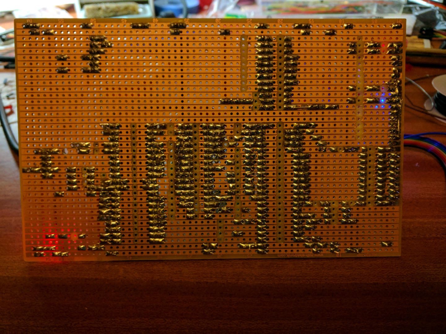
I cobbled it together on breadboards as a quick proof of concept, then put it on stripboard.

Image

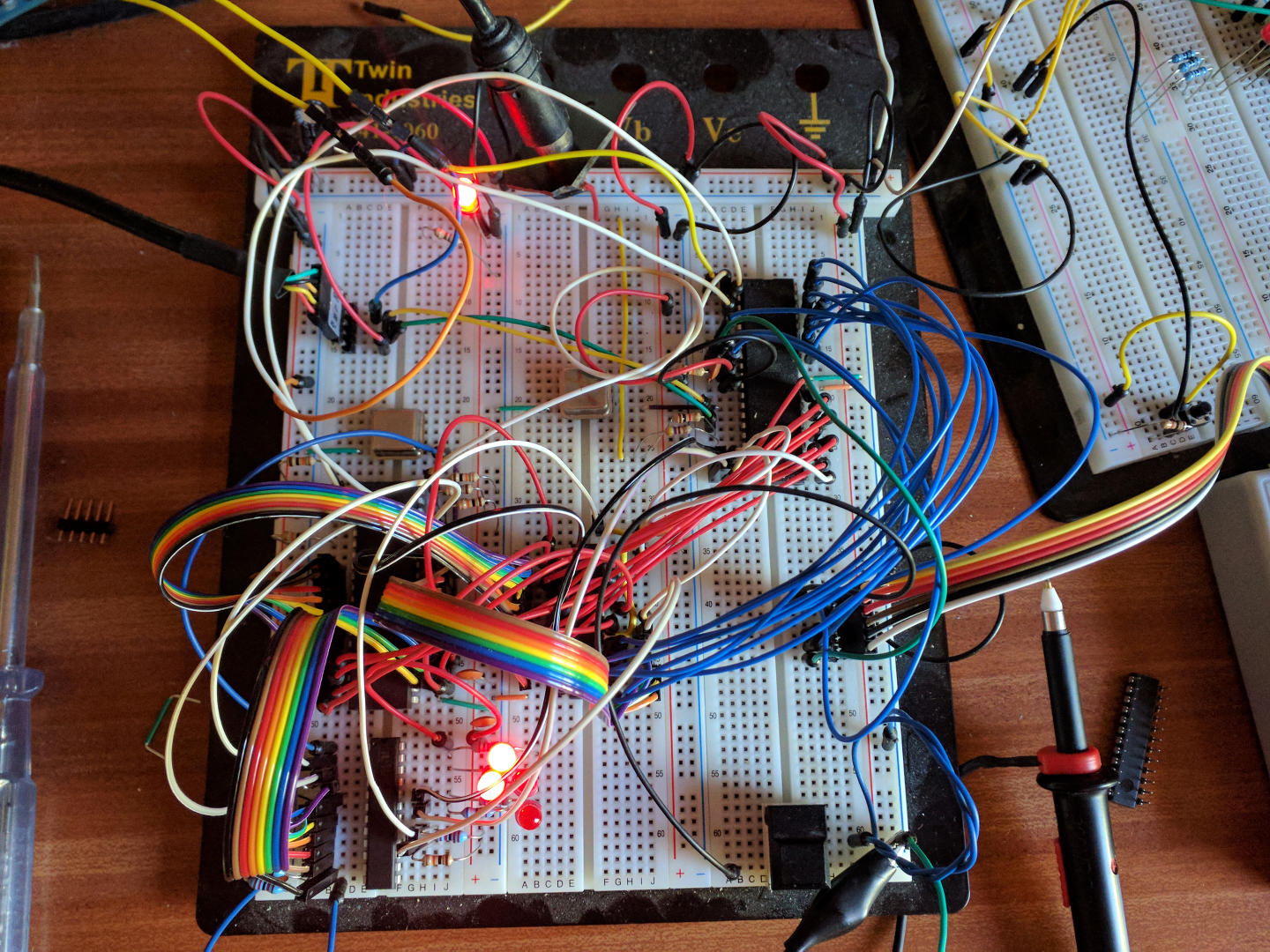
The Ugly Mess of wires!


Image

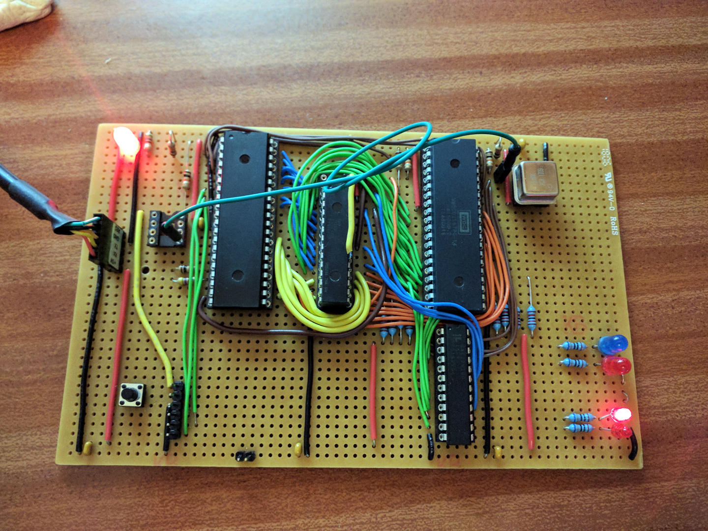
To give you an idea of the chips, from left to right: ATmega 1280p, 64KB RAM (2 x 32Kx8 stacked, yellow wire is the chip select from the top-one), and the 65c02 and below that is a Lattice GAL 22v10.

So no ROM - the ATmega pokes code into the top 256 bytes and can control the BE, Rdy, Reset and IRQ lines to the 6502. (It also reads the Rdy line which is the signal that the 6502 wants to send data to the ATmega. ATmega provides video 320x240x1 PAL composite), serial and soon SD card via SPI. I have 2 spare pins on the ATmega which I may use to implement a PS/2 keyboard interface.

The greenish floating wire is carrying the 16Mhz clock from the 6502 to the ATmega only because I only have one 16Mhz crystal osc. (yet another surprise that it works - it's probably bleeding 16Mhz all over the place, but it works!)

I started it at 2Mhz and was nicely surprised when it got to 16Mhz. It's ran an overnight memory test (250,000 passes) without any issues (the RAM is 12ns though)

The GAL decodes A15 for the 2 RAM chip selects and a page of IO at $FE00 (which the only thing connected to is that 5mm red LED) and qualifies read and write to the memory from the cpu + ph2 - the usual stuff.

I had intended to stick a 65c22 on it, but made a bit of an oops with the chip positioning and didn't leave quite enough room to the right, although I have seriously considered straightening the pins and mounting a 65c22 vertically, but I don't really need one for this experiment. I might stick a latch and some LEDs on it though.

So my plan is to play with this for a while, then make an '816 version then PCBs. (and invest in some "proper" 14Mhz crystal oscs! :-)

Cheers,

-Gordon
--
Gordon Henderson.
See my Ruby 6502 and 65816 SBC projects here: https://projects.drogon.net/ruby/
User avatar
BigEd
Posts: 11463
Joined: 11 Dec 2008
Location: England
Contact:

Re: 65c02 at 16Mhz

Post by BigEd »

I like it!
User avatar
floobydust
Posts: 1394
Joined: 05 Mar 2013

Re: 65c02 at 16Mhz

Post by floobydust »

Very nice! I'm also planning to make a SBC with mostly PLCC parts and run upwards of 16MHz with the W65C02. My last project used an Atmel ATF22V10. Oddly (but most logically) I also use $FE00 for an I/O page, even on the SBC I designed back in the late 80's. My GAL config provides 8- 32-byte wide I/O addresses, qualified memory (or I/O) read and write signals and a RAM and ROM select (using 32KB RAM and 32KB ROM). Your use of the Atmel 1280p is interesting... I think having one of those configured as an 80-column text display and a PS/2 keyboard interface would likely be sufficient in place of a UART console. Having it provide a boot loader is also nice.
User avatar
cbmeeks
Posts: 1254
Joined: 17 Aug 2005
Location: Soddy-Daisy, TN USA
Contact:

Re: 65c02 at 16Mhz

Post by cbmeeks »

Very nice. I'm curious...does the ATmega respond to external pin changes at 16MHz? In other words, is it providing ROM at 16MHz or any type of chip select?

Oh, curious to see what the undercarriage looks like. :-D (the stripboard that is...lol)
Cat; the other white meat.
User avatar
drogon
Posts: 1671
Joined: 14 Feb 2018
Location: Scotland
Contact:

Re: 65c02 at 16Mhz

Post by drogon »

cbmeeks wrote:
Very nice. I'm curious...does the ATmega respond to external pin changes at 16MHz? In other words, is it providing ROM at 16MHz or any type of chip select?

Oh, curious to see what the undercarriage looks like. :-D (the stripboard that is...lol)
The ATmega 1284p (must correct my OP) isn't a ROM as such. At power on, it holds the 6502 in reset, with BE and Rdy also held low. Then it uses 2 8-bit ports, one for the data bus and one for A0-7. A8-15 are pulled high by resistors. At that point, the ATmega has 256 bytes of ram to poke about with which is mapped to $FF00-$FFFF on the 6502. So it pokes in some code + vectors, then lifts Rdy, BE then finally reset and the 6502 boots.

At any time the ATmega can pull Rdy low, then BE a few µS later (I think I need to wait for the current instruction to finish before pulling BE low although I've not found any definitive documentation on that yet), then the 6502 is paused and the ATmega can see the RAM (it tristates it's 2 8-bit buses when the 6502 has control). Then the ATmega can un-pause the 6502, etc.

So the 6502 can re-locate the first stage boot down to $0400 (arbitrary choice), then write a command into the shared RAM and WFI. At that point, the ATmega has been polling the Rdy pin (in input mode), pulls BE low, gets the data from the shared region, writes stuff back, releases BE and pulls IRQ low and releases it when it sees Rdy going high - the 6502 wakes up and off it goes. I've more work to do in that department, but I've tested it all in-principle and it works OK.

As for the undercarriage - it's not pretty :)

Image

Cheers,

-Gordon
--
Gordon Henderson.
See my Ruby 6502 and 65816 SBC projects here: https://projects.drogon.net/ruby/
User avatar
drogon
Posts: 1671
Joined: 14 Feb 2018
Location: Scotland
Contact:

Re: 65c02 at 16Mhz

Post by drogon »

floobydust wrote:
Very nice! I'm also planning to make a SBC with mostly PLCC parts and run upwards of 16MHz with the W65C02. My last project used an Atmel ATF22V10. Oddly (but most logically) I also use $FE00 for an I/O page, even on the SBC I designed back in the late 80's. My GAL config provides 8- 32-byte wide I/O addresses, qualified memory (or I/O) read and write signals and a RAM and ROM select (using 32KB RAM and 32KB ROM). Your use of the Atmel 1280p is interesting... I think having one of those configured as an 80-column text display and a PS/2 keyboard interface would likely be sufficient in place of a UART console. Having it provide a boot loader is also nice.
Thanks.

Currently the GAL (Lattice from Chinashire - I have some Atmel ones but nothing to program them with - Grr, however the ones from China/ebay are all board pulls, very clean and probably only programmed once - all 10 in the pack I bought work fine!) anyway - A8-15 is fed into the GAL. I can take in A7 if needed and possibly A6, but just one line should be enough to wire up 2 x 65c22's but there's plenty of scope there. (and I've just put a latch and 8 LEDs onto it - which is more than I need for some debugging until I get print going)

I didn't want ROM - they're just not fast enough now and I didn't want to go to the bother of wait states, etc.

It's an ATmega 1284p - I don't think I can get 80 columns out of it - I get 40 in 320-240 graphics mode which uses ~9K of it's 16K RAM. that's running an 8Mhz dot clock via the 2nd SPI port - it takes an interrupt every 64µS for each horizontal scan line.

Cheers,

-Gordon
--
Gordon Henderson.
See my Ruby 6502 and 65816 SBC projects here: https://projects.drogon.net/ruby/
User avatar
drogon
Posts: 1671
Joined: 14 Feb 2018
Location: Scotland
Contact:

Re: 65c02 at 16Mhz

Post by drogon »

Now with added blinkenlights:

https://youtu.be/0nrVC7XUgZs


Enjoy :)

-Gordon
--
Gordon Henderson.
See my Ruby 6502 and 65816 SBC projects here: https://projects.drogon.net/ruby/
User avatar
Drass
Posts: 428
Joined: 18 Oct 2015
Location: Toronto, ON

Re: 65c02 at 16Mhz

Post by Drass »

drogon wrote:
At any time the ATmega can pull Rdy low, then BE a few µS later (I think I need to wait for the current instruction to finish before pulling BE low although I've not found any definitive documentation on that yet).
IIRC, BE is an asynchronous signal, and will tri-state the bus immediately. So, yes, you’d want to wait until RDY has paused the CPU before asserting it. RDY will take effect on the next fall of PHI2 after it goes low, so waiting for a cycle is enough — and that’s just 62.5ns at 16MHz! But certainly there is no harm in waiting longer if speed is not an issue. (If using the NMOS 6502 you’d have to wait until a read cycle completes before pulling BE low).

EDIT: Corrected RDY
Last edited by Drass on Sat Nov 10, 2018 11:33 am, edited 1 time in total.
C74-6502 Website: https://c74project.com
User avatar
drogon
Posts: 1671
Joined: 14 Feb 2018
Location: Scotland
Contact:

Re: 65c02 at 16Mhz

Post by drogon »

Drass wrote:
drogon wrote:
At any time the ATmega can pull Rdy low, then BE a few µS later (I think I need to wait for the current instruction to finish before pulling BE low although I've not found any definitive documentation on that yet).
IIRC, BE is an asynchronous signal, and will tri-state the bus immediately. So, yes, you’d want to wait until RDY has paused the CPU before asserting it. RDY will take effect on the next rise of PHI2 after it goes low, so waiting for a cycle is enough — and that’s just 62.5ns at 16MHz! But certainly there is no harm in waiting longer if speed is not an issue. (If using the NMOS 6502 you’d have to wait until a read cycle completes before pulling BE low).
Well... I have the definitive documentation now - in the form of an email from Bill Mensch himself. Essentially BE low without or before RDY going low is not the way to do it. I only did it by accident on my system and was surprised that it did work - going to do some more checking, but not too much more. Take RDY low, pause (a cycle which on the ATmega, even at 16Mhz in a C program is essentially the next instruction, but a single NOP won't hurt) then take BE low.

I'm only looking at WDC 65C02S chips here, so the old NMOS or any other variant isn't an issue.

Cheers,

-Gordon
--
Gordon Henderson.
See my Ruby 6502 and 65816 SBC projects here: https://projects.drogon.net/ruby/
User avatar
Drass
Posts: 428
Joined: 18 Oct 2015
Location: Toronto, ON

Re: 65c02 at 16Mhz

Post by Drass »

Sorry Gordon. Got my wires crossed last night ... correction: RDY pauses the CPU on the FALL of PHI2 (not the rise as I said above). Quoting from the 65C02 datasheet regarding RDY:

“A negative transition to the low state prior to the falling edge of PHI2 will halt the microprocessor with the output address lines reflecting the current address being fetched. This assumes the processor setup time is met.”

I don’t think this changes anything in your application, but I best clean up the post above to keep things straight.

Cheers.
C74-6502 Website: https://c74project.com
User avatar
BigEd
Posts: 11463
Joined: 11 Dec 2008
Location: England
Contact:

Re: 65c02 at 16Mhz

Post by BigEd »

I think we're saying that RDY is sampled on the falling edge. I wish WDC would write more clearly...
czuhars
Posts: 13
Joined: 12 Apr 2016

Re: 65c02 at 16Mhz

Post by czuhars »

Fantastic work, and thanks for sharing the beefy pics.

Relevant to me, you buried the lead with using the Mega for video. I'm at a point in my project where I'm looking into various methods to generate different video modes. Using my Arduino Mega2560 was one idea.
With yours, are you using a library like tvOut? Or did you roll your own? Just curious how your video is set up.

Again, nice work and thanks for sharing.
User avatar
drogon
Posts: 1671
Joined: 14 Feb 2018
Location: Scotland
Contact:

Re: 65c02 at 16Mhz

Post by drogon »

czuhars wrote:
Fantastic work, and thanks for sharing the beefy pics.

Relevant to me, you buried the lead with using the Mega for video. I'm at a point in my project where I'm looking into various methods to generate different video modes. Using my Arduino Mega2560 was one idea.
With yours, are you using a library like tvOut? Or did you roll your own? Just curious how your video is set up.

Again, nice work and thanks for sharing.
I ought to reduce the image sizes - I thought the forum here would display shrunken ones, but it doesn't seem to (or I've not worked out how)

The videos:

https://youtu.be/09zhGUbVxdU
and
https://youtu.be/1Iv-bDmkW2M

I rolled my own code, however it was based on the Arduino tvOut library to some extent. There are lots of variants out there, but all use the same 2-resistor combo. I use the SPI channel on the 2nd USART which avoids vertical gaps.

I've also done Tv/Video stuff in my dim and distant past so knowing what a video signal is expected to look like helped a little. (I don't use the Arduino software, but do everything purely in C). I also wanted bitmapped graphics, so it comes out at 320x240 pixels, or 40x30 characters with an 8x8 font. (could be less lines if required).

It's not without issues that I only discovered when using a real tube monitor - it wobbles - and further research showed that this is due to interrupt latency on the ATmega - it's not as RISC as it's made out to be and if it's executing an instruction that takes 2 cycles, then it will wait until that instruction has completed before servicing the interrupt. There are some tricks you can employ but it needs a few lines of ASM code to essentially take the timer/cpu/interrupt skew and lock them together, however I've not quite gotten that sorted yet (all my code is in C and I've not yet dived into the world of AVR assembler).

I think the timing fixup code comes from our very own Oneironaut/Vi-20 Jet Pack member on another forum under another name but I could be wrong...

I'm probably not going to continue with my ATmega video solution when I move to the 65816, but to use a Raspberry Pi instead. In many ways it'll be easier and I get colour, but I'm going to limit it to a suitably retro 640x480 VGA with a limited pallet - for no reason other than there is really no point trying to get a little 8/16 bit micro to do anything sensible at Full-HD.

I'm slowly blogging this on my own website, but not actually hit the publish button yet - want to make sure I have a good few pages down before I do that, but will publish links and summarys here when the time comes.

Cheers,

-Gordon
--
Gordon Henderson.
See my Ruby 6502 and 65816 SBC projects here: https://projects.drogon.net/ruby/
User avatar
Dr Jefyll
Posts: 3525
Joined: 11 Dec 2009
Location: Ontario, Canada
Contact:

Re: 65c02 at 16Mhz

Post by Dr Jefyll »

drogon wrote:
I ought to reduce the image sizes - I thought the forum here would display shrunken ones, but it doesn't seem to (or I've not worked out how)
The forum software will display a thumbnail if you include the image as an attachment to your post. But the images you posted above aren't hosted on 6502.org.

Many forum members seem unaware that image attachments are permitted. Consequently, some folks use third-party sites where the images unfortunately won't have much permanence. In contrast, content on 6502.org regularly gets backed up, and will remain intact for future readers to enjoy.
Attachments
attachment uploading.png
In 1988 my 65C02 got six new registers and 44 new full-speed instructions!
https://laughtonelectronics.com/Arcana/ ... mmary.html
User avatar
drogon
Posts: 1671
Joined: 14 Feb 2018
Location: Scotland
Contact:

Re: 65c02 at 16Mhz

Post by drogon »

Dr Jefyll wrote:
drogon wrote:
I ought to reduce the image sizes - I thought the forum here would display shrunken ones, but it doesn't seem to (or I've not worked out how)
The forum software will display a thumbnail if you include the image as an attachment to your post. But the images you posted above aren't hosted on 6502.org.

Many forum members seem unaware that image attachments are permitted. Consequently, some folks use third-party sites where the images unfortunately won't have much permanence. In contrast, content on 6502.org regularly gets backed up, and will remain intact for future readers to enjoy.
I'm aware I can upload. I also run my own servers which are also backed up. I host my own images so I can show others without giving a forum link, nor subjecting them to slow bandwidths or stupid adverts. However I've also used other forums which will grab and create thumbnails on the fly.

-Gordon
--
Gordon Henderson.
See my Ruby 6502 and 65816 SBC projects here: https://projects.drogon.net/ruby/
Post Reply