POC V1.0
Posted: Fri Dec 25, 2009 7:19 pm
Here are some more pictures of my first-design POC computer:
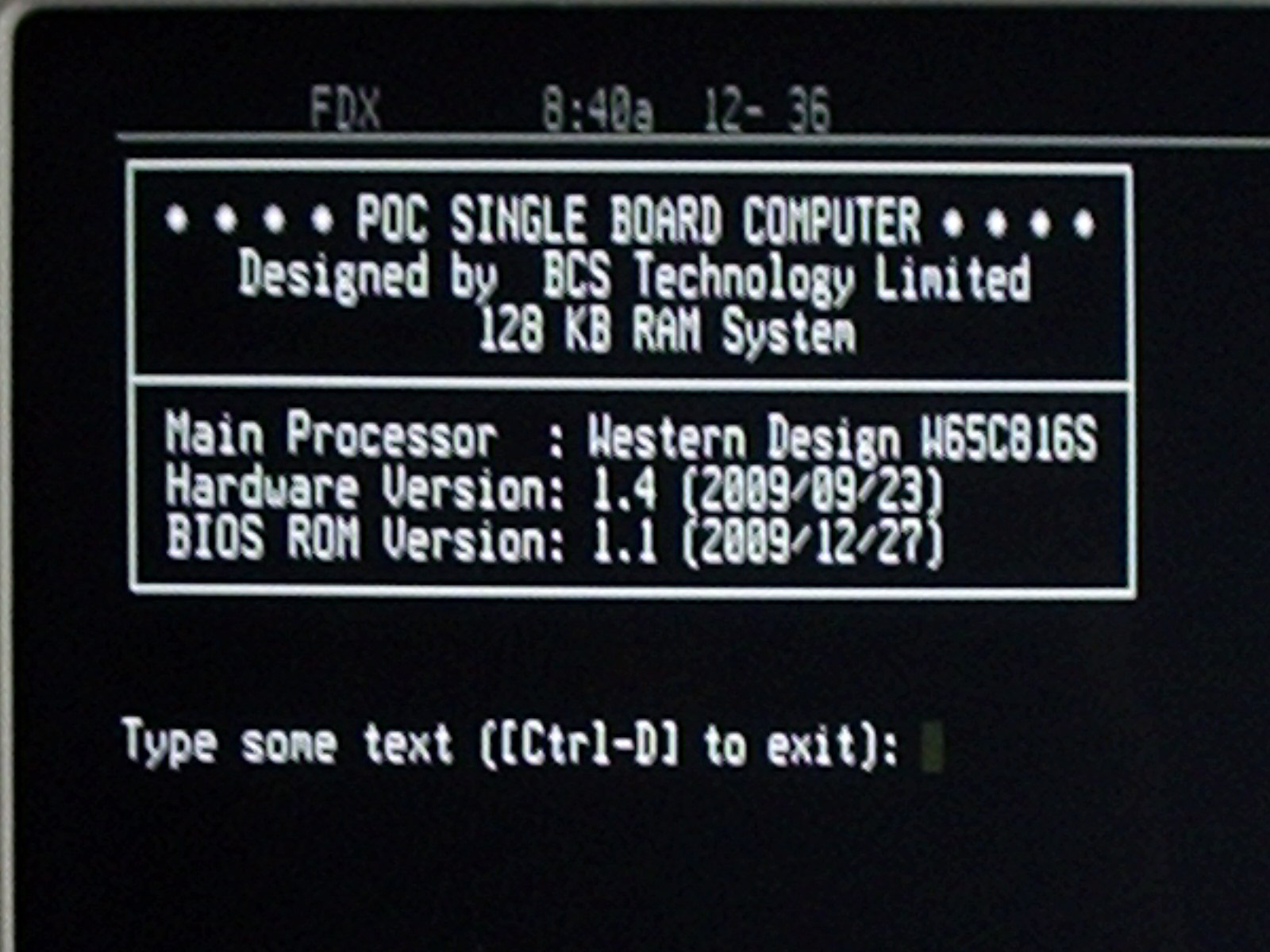
which should be sufficient to check for the presence of activity on the buses. If that test fails then I'll have to use a NOP generator to see why things aren't working. Otherwise, I will burn more complicated code into the EPROM to generate a display on a terminal screen.
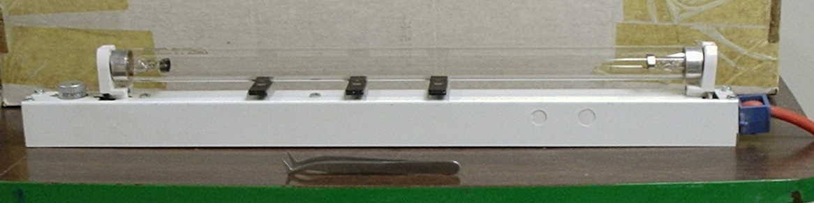
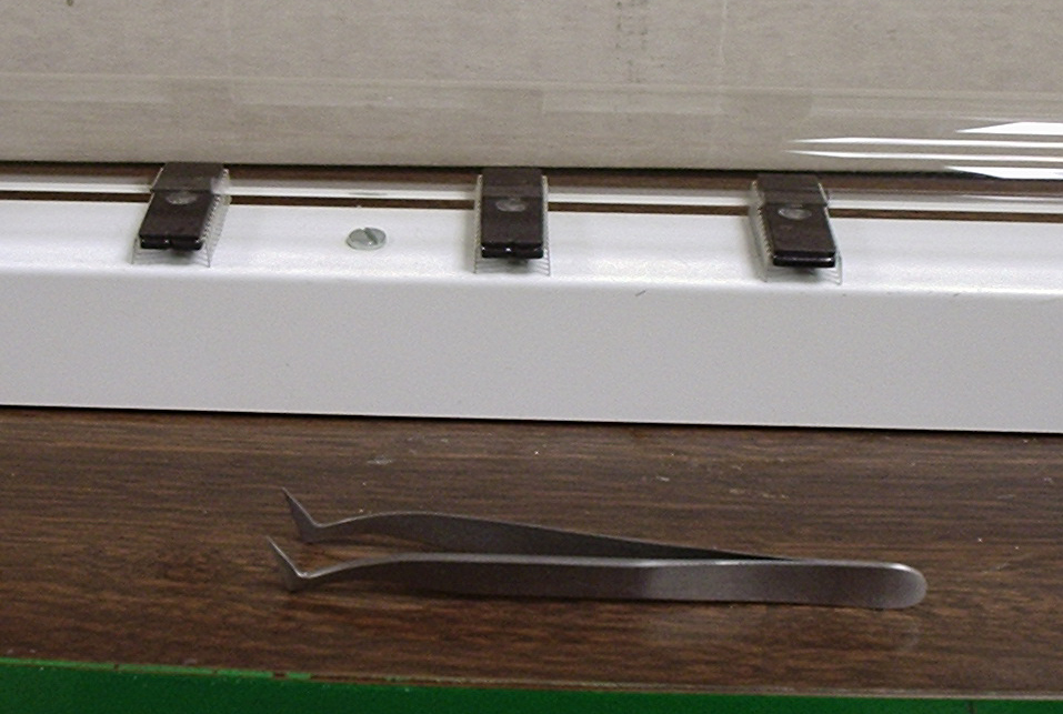
Speaking of EPROMs, here's what I use to erase them. This device, of course, represents a significant financial investment:
This rig will erase a whole bunch of EPROMs in a little more than 10 minutes. The white background in the first picture is actually the protective cover that I place over the eraser to avoid stinking up the place with ozone and developing a mid-winter suntan. The eraser is nothing more than an old under-the-cabinet kitchen light fixture fitted with an antiseptic UV fluorescent lamp. I modified the fixture to increase the space between the lamp and the fixture housing so there's sufficient room for the EPROMs. As can be seen, a lot of EPROMs can be erased at one time with this contraption.
In keeping with the general motif of this device, I use, of course, a cheap kitchen timer to tell me when the erasing operation is done. Some day I might actually get fancy and rig up a timer to automatically turn it off for me.
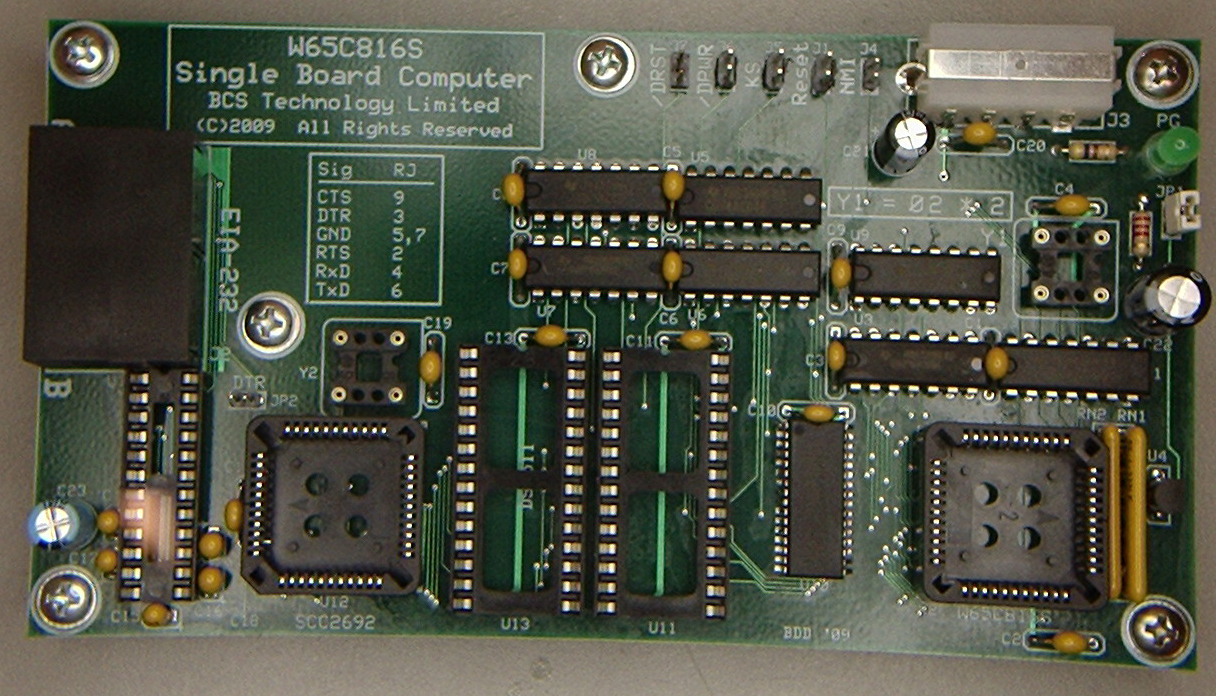
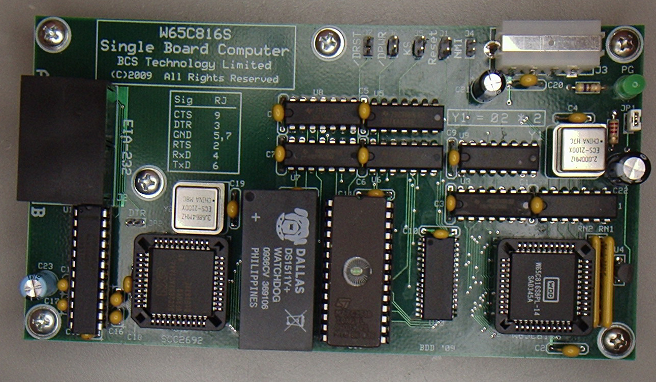
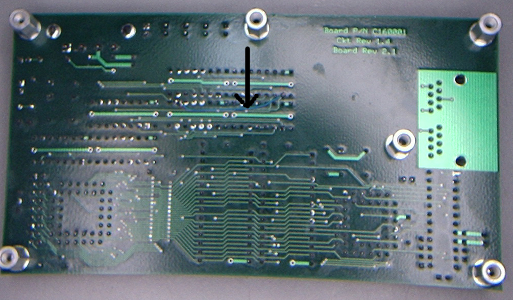
- PCB with SRAM and glue logic installed. As can be seen, I wasn't stingy with the decoupling capacitors.
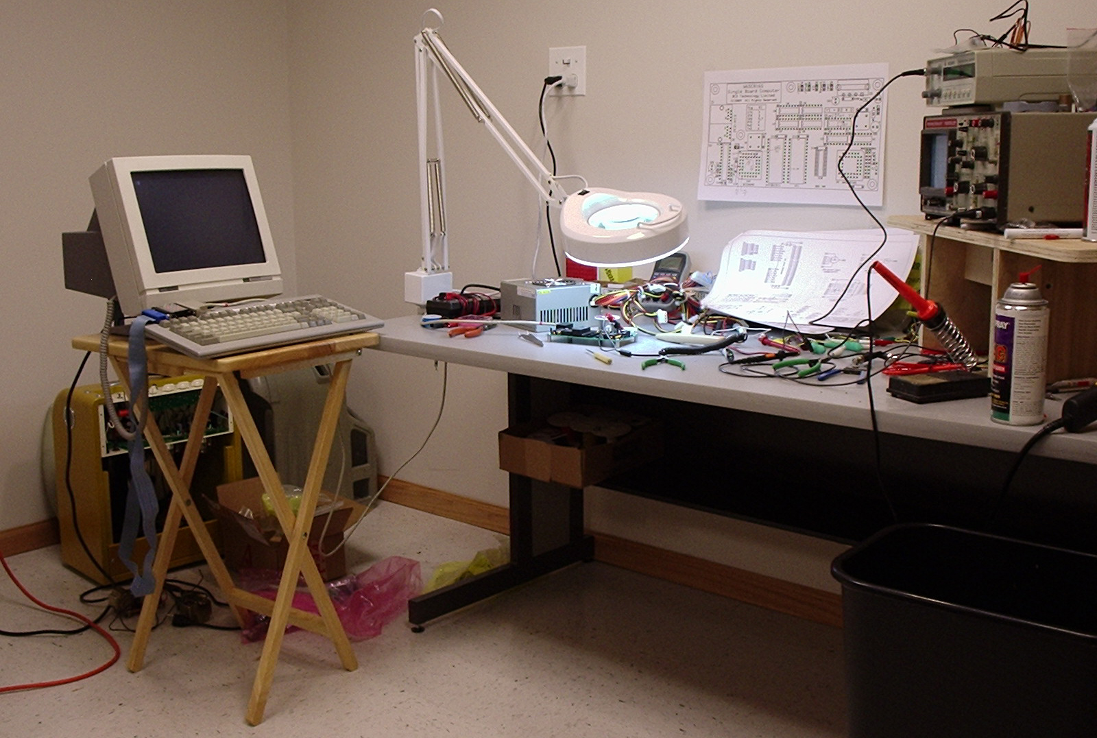
PCB undergoing initial testing.
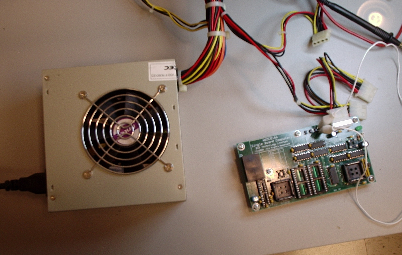
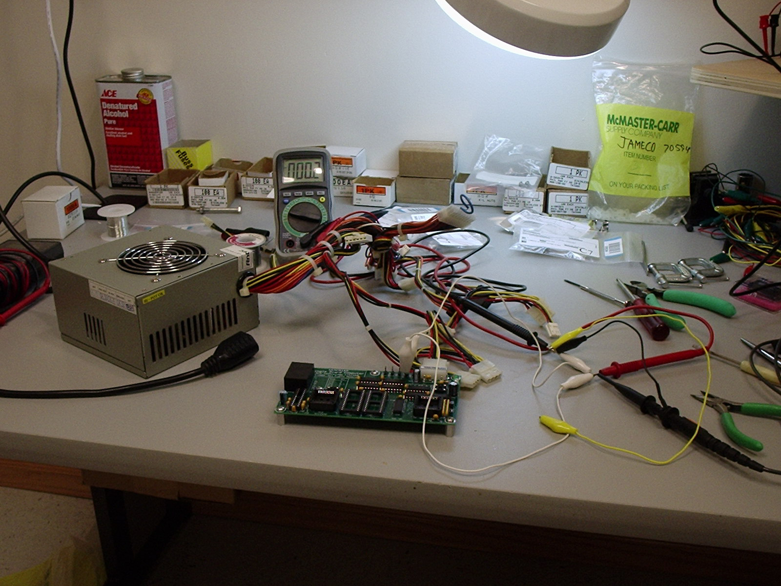
My technically advanced test setup. I use an old Antec PC power supply as the power source. The power input connector on the PCB is a standard Molex part used on 5-1/4 inch disk drives. In this view, I have the 'scope and DMM connected to the /RESET line to observe its behavior.
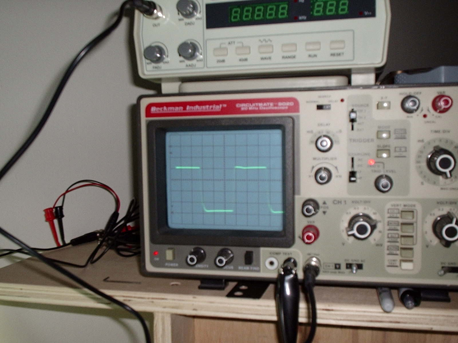
The Ø2 clock signal as seen on my ancient Beckman Industrial 20 MHz 'scope. The 'scope is set to 0.1 volts/division, with the probe set to 10:1 attenuation. The display clearly shows that the Ø2 signal is flipping between 0 and 5 volts, just as it should be. The slight distortion of the square wave reflects the bandwidth limitations of the 'scope. Whaddya expect from something that's older than dirt and still has the original CRT?
The fully populated PCB ready for launch.
Code: Select all
00E000  4C 00 E0  JMP $E000

00FFFC 00 E0 .BYTE $E000Speaking of EPROMs, here's what I use to erase them. This device, of course, represents a significant financial investment:
This rig will erase a whole bunch of EPROMs in a little more than 10 minutes. The white background in the first picture is actually the protective cover that I place over the eraser to avoid stinking up the place with ozone and developing a mid-winter suntan. The eraser is nothing more than an old under-the-cabinet kitchen light fixture fitted with an antiseptic UV fluorescent lamp. I modified the fixture to increase the space between the lamp and the fixture housing so there's sufficient room for the EPROMs. As can be seen, a lot of EPROMs can be erased at one time with this contraption.
In keeping with the general motif of this device, I use, of course, a cheap kitchen timer to tell me when the erasing operation is done. Some day I might actually get fancy and rig up a timer to automatically turn it off for me.