Page 5 of 8
Posted: Wed Dec 07, 2011 8:04 pm
by ElEctric_EyE
I must've had too many windows open when I said HESMON was replacing a $4C (JMP) with a $20 (JSR). After looking at it again, it is storing a $20 where a $20 already is... Still a curiousity but I don't have time for it right now.
...It's all ROMs and I/O...You might check to see whether the code plays around with memory location $1, the memory mapping "register".
It does store a #$37 at location $01, enabling Basic, Kernal ROMs and I/O. Also this is an image that I stored years ago on a C64 5 1/4" floppy right alongside of Micromon. I'm not sure how I got it, although I think I typed it in from Compute! or Compute's Gazette and the image does work in VICE.
...I have only to make a separate table for the text strings and opcodes, and As65 will be able to assemble it and create the .bin for the bin2coe to create the ROM. Then I'll try substituting 2 routines with 2 of mine, namely character in and character out, and maybe will see some sort of life.
__________________________________________________________________________________________________________________________
In the meantime today I spent a greater portion trying to figure out a problem I am having with my ATTBUTE routine. It involves using a LDA COLTABLE,X. COLTABLE=$FFFFC980. The original code does not work. It's plotting all zero values. I've tried replacing the label with the actual address, also tried changing the address to $FFFFE000 (middle of nowhere within 16K blockRAM) with no luck...
Code: Select all
ATTBUTE     LDA CHRATTR	      ;get color from bits 0,1,2,3
	          AND #$000F
	          ASL A
	          ASL A		          ;multiple by 4 for easy indexing
	          TAX
	          LDA COLTABLE,X
	          STA PXLCOL1
	          INX
	          LDA COLTABLE,X
	          STA PXLCOL2
	          INX
	          LDA COLTABLE,X
	          STA PXLCOL3
Today, I found out what does work: If I replace LDA COLTABLE,X with LDA COLTABLE, LDA COLTABLE+1, LDA COLTABLE+2 it does lookup and plot the correct color, so no problem with blockRAM (there was one with 8Kx16). I'm thinking there's a problem with the 65Org16 core using Absolute Indexed with X. I will double check this against Arlet's original...
BTW, when it comes time to make room for HESMON and original zero page variables, I will be moving my routines from $FFFFC000 to $FFFFD000 and moving all my zero page variables to $00000100. Posting this now makes me realize I need to re-allocate all original stack variables from $0100-$01FF to $00010000-$0001FFFF...
Posted: Wed Dec 07, 2011 9:30 pm
by ElEctric_EyE
...In the meantime today I spent a greater portion trying to figure out a problem I am having with my ATTBUTE routine. It involves using a LDA COLTABLE,X. COLTABLE=$FFFFC980. The original code does not work. It's plotting all zero values. I've tried replacing the label with the actual address, also tried changing the address to $FFFFE000 (middle of nowhere within 16K blockRAM) with no luck...
I've looked at the .bin and it seems the problem lies within As65 if I'm not mistaken.
I am observing an opcode $B5 (LDA ZP,x) when it should be an opcode $BD (LDA a,x). Bitwise, please help!
Posted: Wed Dec 07, 2011 11:59 pm
by BitWise
Is address argument to the LDX ...,X an external symbol or a constant value?
You can insert a '|' or '!' before the address to force the assembler to generate an ABS,X mode rather a ZP,X
For example LDA |$80,X should generate BD 80 00 instead of B5 80. The same should work for the 65Org16 mode.
Posted: Thu Dec 08, 2011 12:29 am
by ElEctric_EyE
Thanks for a quick response

Is address argument to the LDX ...,X an external symbol or a constant value?...
Not an LDX...,X. It is an LDA ...,X.
Last test I used a constant of $FFFFE000,X no labels... Instead of translating the LDA $FFFFE000,X to a 00BD, FFFF, E000; it is translating it to 00B5,E000 according to my hex editor.
Posted: Thu Dec 08, 2011 10:51 am
by ElEctric_EyE
Ok, that worked. Thanks!
Posted: Tue Dec 13, 2011 12:52 am
by ElEctric_EyE
I've done some more digging into the original 8bit C-64 Hashmon code...
Using VICE C-64 emulator on PC and running the Hashmon code is proving invaluable. I instantly found the main loop using the VICE monitor. It starts @ $C24D and is a very short loop with just a few other JSRs JMP's that branch out. I still need to follow these to their ends, but right now I am aiming for a startup screen that jives with the original Hashmon. This will at least prove my output character routine is sufficient. Also, I've found within the main loop, Hashmon reads characters typed in from the keyboard stored at $39.
There are 2 Indirect JMP's within the 4K worth of code which concern me:
a JMP ($00C1), and a JMP ($0120). I will figure them out eventually.
I found the Indirect Indexed screen matrix pointer @$D1, $D2. Directly related is the $F3, $F4 Indirect Indexed pointer to screen color RAM. These are some of the "constant" variables which are very important. Not so much the screen color RAM though.
I am finding there is alot I would like to delete from the original code. Maybe trim it to 1/2 the size it is. No need for tape storage etc... Alot of variables saved for basic and kernal, which are not needed here.
Posted: Tue Dec 13, 2011 6:47 pm
by ElEctric_EyE
...You can insert a '|' or '!' before the address to force the assembler to generate an ABS,X mode rather a ZP,X
For example LDA |$80,X should generate BD 80 00 instead of B5 80. The same should work for the 65Org16 mode.
Your new
update works, so no more need for '|' or '!'. Thanks!
Posted: Fri Dec 16, 2011 1:26 am
by ElEctric_EyE
I've come across
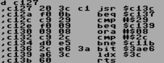
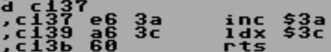
6 instances like the one below. These are the last inconsistencies I have left before fully translating HESMON from 8bit 6502 to 16bit 65Org16. This example below is a pic taken from VICE running the original HESMON image and disassembling itself. This is just abit of some tricky coding here. Check out the BEQ's. Almost like the BIT $3AE6 ($2C, $E6, $3A)is non function
Code: Select all
eC127:
          	JSR eC13C
          	BEQ eC137
          	CMP #$29
          	BEQ eC139
          	ORA #$08
          	CMP #$2C
          	BNE eC11B
          	BIT $3AE6
eC139:
          	LDX $3C
          	RTS
When the CPU sees a BEQ $C137, it looks like this:
Posted: Fri Dec 16, 2011 6:12 am
by teamtempest
I've come across 6 instances like the one below
An old space-saving trick discussed in more detail in this thread:
viewtopic.php?t=1614
Posted: Fri Dec 16, 2011 9:35 pm
by ElEctric_EyE
Excellent. Thanks for pointing that out, I didn't think to check this site, duh! Using .BYTE $2C made it so I could use the labels that As65 was looking for.
Done creating a workable .bin image...
Posted: Tue Dec 20, 2011 1:31 am
by ElEctric_EyE
Thinking back to the equivalent $FFD2 CHROUT routine on the C-64, I think I've got my routine down pretty close. And thanks to TeamTempest for contributing.
Sorry for the length, but I have now incorporated the PLTPOS and ATTBUTE routines
within the PLTCHR routine. Plot Enable is now a bit value...
Also, all 16bits of the databus are used to define a character for the 8bit video TFT. The bit placements are commented within the assembly. Simply put, the lower 7 bits define the ASCII character, and bits 8thru15 are character plot enable, size, color and font attributes (1,3,4, & 1 bits respectively)...
The PLTCHR routine still needs just abit of final fine tuning to detect when to increment the Y Plot value, after reaching max X with variable character sizes, in order to continue plotting to the second and consecutive lines. Working...
I thought I would post the code now, even though it is incomplete, in order to show how many ASLs and LSR's are needed.
Code: Select all
PLTCHR      STA CHR           ; Plot Character Subroutine variable (1-7) H and V size
            TYA               ; save all reg's
            PHA
            TXA
            PHA

ATTBUTE     AND #%00000111100000000
	          LSR A             ;get color VALUE from bits 8,9,10,11
            LSR A
            LSR A
            LSR A
            LSR A
            LSR A             ;multiply by 4 for easy indexing
	          TAX
	          LDA COLTABLE,X
	          STA PXLCOL1
	          INX
	          LDA COLTABLE,X
	          STA PXLCOL2
	          INX
	          LDA COLTABLE,X
	          STA PXLCOL3

	          LDA CHR           ;check bits 12,13,14 for size
	          AND #%0111000000000000
	          LSR A
	          LSR A
	          LSR A
	          LSR A
            LSR A
            LSR A
            LSR A
            LSR A
            LSR A
            LSR A
            LSR A
            LSR A		          ;make size 1x through 7x, no size 0!
	          STA XWIDTH
	          STA YWIDTH

	          LDA CHR    	      ;check font bit 15, 1=C64 , 0=3x5
	          AND #%1000000000000000
	          CMP #$8000
	          BEQ n64
            LDA #$08
            STA PATROW
            STA CHRXLEN
            STA CHRYLEN

            LDA #$CA00
            STA CHRBASE
		        LDA #$0080
		        STA SENTINEL
	          JMP porc

n64	        LDA #$04
            STA CHRXLEN
            LDA #$05
            STA PATROW
	          STA CHRYLEN
            LDA #$CD00
            STA CHRBASE
		        LDA #$0800
		        STA SENTINEL

porc        LDA CHR		        ;test PE bit 7 for plot or clear
            AND #%0000000010000000
            CMP #$80
		        BNE plot2
	          LDA SCRCOL1
	          STA TMPCOL1
	          LDA SCRCOL2
	          STA TMPCOL2
	          LDA SCRCOL3
	          STA TMPCOL3
	          JMP PLTPOS
plot2	      LDA PXLCOL1
	          STA TMPCOL1
	          LDA PXLCOL2
	          STA TMPCOL2
	          LDA PXLCOL3
	          STA TMPCOL3

PLTPOS      LDA #$2A          ;set x address
	          STA DCOM
            LDA XPOS
            PHA
            LSR A
            LSR A
            LSR A
            LSR A
            LSR A
            LSR A
            LSR A
            LSR A
            STA DDAT          ;X START MSB
            PLA
            AND #$00FF
            STA DDAT          ;X START LSB

            LDA XPOS
            CLC
            LDX XWIDTH
AC          ADC CHRXLEN
            DEX
            BNE AC
            STA XPOS          ;UPDATE X POSITION
            INC XPOS          ;NEXT CHR WILL GO HERE
            SEC
            SBC #$01
            PHA
            LSR A
            LSR A
            LSR A
            LSR A
            LSR A
            LSR A
            LSR A
            LSR A
            STA DDAT          ;X END MSB
            PLA
            AND #$00FF
            STA DDAT          ;X END LSB

            LDA #$2B          ;set y address
            STA DCOM
	          LDA YPOS
            PHA
            LSR A
            LSR A
            LSR A
            LSR A
            LSR A
            LSR A
            LSR A
            LSR A
            STA DDAT          ;Y START MSB
            PLA
            AND #$00FF
            STA DDAT          ;Y START LSB

            LDA YPOS
            CLC
            LDX YWIDTH
AD          ADC CHRYLEN
            DEX
            BNE AD
            SEC
            SBC #$01
            PHA
            LSR A
            LSR A
            LSR A
            LSR A
            LSR A
            LSR A
            LSR A
            LSR A
            STA DDAT          ;Y END MSB
            PLA
            AND #$00FF
            STA DDAT          ;Y END LSB

CACALC      LDA #$2C          ; Prepare TFT to Plot
            STA DCOM

            LDA CHR
            AND #$7F          ; an ascii char ? - ATTRIBUTE INFO
            CMP #$0D
            BNE nnull
            LDX #$00
            STX XCHRPOS
            INC YCHRPOS
            LDA #$00          ; make undefined char's a defined zero (space character)
nnull       SEC
            SBC #$20
            ASL A             ; * 2
            ASL A             ; * 4
            ASL A             ; * 8
            CLC
            ADC CHRBASE       ; add pointer to base either CA00 (C64)  or CD00(3x5) (carry clear)
            TAY

loop7       LDA XWIDTH        ; plot row repeat count (1-7)
            STA PIXROW
loop4       LDA CHARPIX,Y     ; $FFFFCA00(c64) or $FFFFCD00(3x5)
            ASL A             ;
            ASL A             ;
            ASL A             ;
            ASL A             ;
            ASL A             ;
            ASL A             ;
            ASL A             ;
            ASL A             ; shift out upper 8 bits, don't care for 8-bit byte character font
            ORA SENTINEL      ; $0080 (C64) or $0800 (3x5)

            ASL A             ; get a pixel
loop5       PHA               ; save remaining pixel row data
            LDX YWIDTH        ; plot column repeat count (1-7) (same as PLTHGT?)
            BCC xwnp          ; b: clear ('blank')

xwp         LDA TMPCOL1
            STA DDAT          ; plot RED pixel TFT data
            LDA TMPCOL2
            STA DDAT          ; plot GREEN pixel TFT data
            LDA TMPCOL3
            STA DDAT          ; plot BLUE pixel TFT data
            DEX
            BNE xwp
            BEQ nxtpix        ; b: forced

xwnp        LDA SCRCOL1
            STA DDAT          ; plot RED "blank" pixel TFT data
            LDA SCRCOL2
            STA DDAT          ; plot GREEN "blank" pixel TFT data
            LDA SCRCOL3
            STA DDAT          ; plot BLUE "blank" pixel TFT data
            DEX
            BNE xwnp

nxtpix      PLA               ; get pixel row data back
            ASL A             ; another pixel to plot ?
            BNE loop5         ; b: yes (sentinel still hasn't shifted out)

            DEC PIXROW        ; repeat this row ?
            BNE loop4         ; b: yes

            INY
            DEC PATROW        ; another pattern row to plot ?
            BNE loop7         ; b: yes

            PLA
            TAX
            PLA
            TAY               ;reload reg's
            RTS
Posted: Tue Dec 20, 2011 10:29 am
by BigEd
Thanks - overall, you've got a 12, a 6 and some 8-bit shifts, which is worth knowing.
I did have a thought: you could do right shifts with MPY and XBA. For example, getting bits from position $0F00 into position $003c would be
Admittedly, not as quick or easy as
if we had that, but perhaps better than
(Left shifts are more obvious, since they are just a multiply.)
For my modifications, it makes the shifter somewhat less attractive, because I don't offer read-modify-write addressing modes. For your approach with the shift distance in the opcode, the shifter is much more valuable.
For your
I think you can get there faster using
(if you're limited to the present instruction set.)
In any case, it's probably worth writing a macro for multi-bit shifts, so you can use multiple instructions for as long as you have to, and then switch to new opcodes when that becomes possible. And your code becomes more compact and readable.
Cheers
Ed
Posted: Tue Dec 20, 2011 12:48 pm
by ElEctric_EyE
...In any case, it's probably worth writing a macro for multi-bit shifts, so you can use multiple instructions for as long as you have to, and then switch to new opcodes when that becomes possible. And your code becomes more compact and readable.
Cheers
Ed
Good idea.
I had an idea a couple days ago. Tell me if it's worth anything...
It would be a cycle counter with programmable start and stop addresses (depending on length of code, 16bit counter should be sufficient). It would be especially useful when comparing the effect of modifying opcodes.
For me, it's a little fuzzy how an internal shift Xtimes can be just as fast as shift 1time. This counter could quantify the effects, I believe.
Posted: Tue Dec 20, 2011 12:56 pm
by BigEd
To answer your second question, the shifter is a single-cycle barrel shifter. It's huge, but fast. I haven't measured the size, but I'll do so. (Done - see below)
For your first question, yes, a performance counter could be very handy - modern CPUs have them. For something as simple as counting cycles, as we're on FPGA, the simplest thing to do is just add a memory-mapped peripheral which is a counter you can start and stop. Once you add performance counters to the CPU, which is easy, you also need to add ways to set and get them, which is going to be a bit less easy. (Things like counting branches, or taken branches, or JSRs, could be interesting.)
Cheers
Ed
Edit: here's the size:
slice counts for Arlet's core (spartan3, 'balanced' synthesis)
8 bit cpu: 247, plus 118 for long distance shifting
16 bit cpu: 360, plus 140
32 bit cpu: 488, plus 268
Posted: Wed Dec 21, 2011 8:39 am
by ElEctric_EyE
Those barrel shifters take some resources! Reminds me of when I was trying to use 16-bit comparators in a CPLD, they also are resource hungry...
On a related note, I'm going to need 2 32bit comparators for the cycle counter. One to toggle the counter on and 1 to toggle the counter off.
For something as simple as counting cycles, as we're on FPGA, the simplest thing to do is just add a memory-mapped peripheral which is a counter you can start and stop...
I'm up abit early, can't sleep...
So as far as bringing the PC out of the cpu, is it as easy as this?:
Code: Select all
module cpu( clk, reset, AB, PC, DI, DO, WE, IRQ, NMI, RDY );

parameter dw = 16;		// data width (8 for 6502, 16 for 65Org16)
parameter aw = 32;		// address width (16 for 6502, 32 for 65Org16)

input clk;					// CPU clock
input reset;				// reset signal
output reg [aw-1:0] AB;	// address bus
input [dw-1:0] DI;		// data in, read bus
output [dw-1:0] DO; 		// data out, write bus
output WE;					// write enable
input IRQ;					// interrupt request
input NMI;					// non-maskable interrupt request
input RDY;					// Ready signal. Pauses CPU when RDY=0
output reg  [aw-1:0] PC;// Program Counter