So if required, a better solution would be to drill a 1/32 hole through each breadboard panel and then connect a bolt throughout the board into the aluminum plate, which in turn is connected to a small wire going back to the ground bus on each board rail.
I guess I will just look at it this way, and consider it a "benefit"...
If I can get this project working in this environment, then transferring to a real PCB is going to be easy as pie later!
Brad
Vulcan-74 - A 6502 Powered Retro MegaProject
-
Oneironaut

- Posts: 734
- Joined: 25 May 2015
- Location: Gillies, Ontario, Canada
- Contact:

Re: Vulcan-74 - A 6502 Powered Retro MegaProject
I think one hole/connection per breadboard won't add much benefit.
I think the best approach is to try to keep the signal lines short, on the same breadboard, as much as possible. And if you have to do longer signal lines, from one breadboard to the other, add one or more ground wires to the same bundle, and stick those close to the ICs where the signals go in & out.
I think the best approach is to try to keep the signal lines short, on the same breadboard, as much as possible. And if you have to do longer signal lines, from one breadboard to the other, add one or more ground wires to the same bundle, and stick those close to the ICs where the signals go in & out.

Re: Vulcan-74 - A 6502 Powered Retro MegaProject
Oneironaut wrote:
I am bracing for the noise that the 65C02 is going to add as well.
Seems, it has that high switching rate as well, and in another project it spewed noise all over an otherwise nice design.
Seems, it has that high switching rate as well, and in another project it spewed noise all over an otherwise nice design.
Oneironaut wrote:
Jeff, I do member you suggestion to use the 163 output version from this post... [...]
found that there was a very slight variance between the counters. [...]
I had to resync with another 574
found that there was a very slight variance between the counters. [...]
I had to resync with another 574
It's worrisome that you had difficulty getting multiple 163's to clock exactly in unison. In your latest design you'll be attempting to get multiple 574's to clock exactly in unison, and it's reasonable to expect that the same difficulty might arise. (I believe your previous "add a 574" solution worked because it resulted in all the video bits getting clocked by a single IC -- not because the IC type changed from 163 to 574.)
It would be good to resolve this challenge of getting a set of 163's (or 574's) on a solderless breadboard to clock exactly in unison, and I have some ideas about that. If the problem can't be resolved then you'll probably be forced to use the 16-bit equivalent to the 574 (I don't recall the part number offhand) in order to ensure that all the video bits get clocked by a single IC.
Oneironaut wrote:
The "glitch" I found in the 163 is that you have to clock in the reset (hold it during the clock transition).
In 1988 my 65C02 got six new registers and 44 new full-speed instructions!
https://laughtonelectronics.com/Arcana/ ... mmary.html
https://laughtonelectronics.com/Arcana/ ... mmary.html
-
BigDumbDinosaur

- Posts: 9428
- Joined: 28 May 2009
- Location: Midwestern USA (JB Pritzker’s dystopia)
- Contact:
Re: Vulcan-74 - A 6502 Powered Retro MegaProject
Arlet wrote:
The key is to visualize currents as going in a loop, with the signal going from A to B, and the return current through ground back from B to A. For best integrity, you want the return path to be as close as possible to the signal path.
Whether an external plate is useful depends on how close it is to the signal, and how much of a detour the current has to take to get on the plate, and back off.
Whether an external plate is useful depends on how close it is to the signal, and how much of a detour the current has to take to get on the plate, and back off.
x86? We ain't got no x86. We don't NEED no stinking x86!
-
Oneironaut
- Posts: 734
- Joined: 25 May 2015
- Location: Gillies, Ontario, Canada
- Contact:
Re: Vulcan-74 - A 6502 Powered Retro MegaProject
Yes, I consider a glitch to be the result of any hardware or software not doing exactly what I want, when I want, and how I want!
... probably why I live an hour from town with no neighbors, don't own a phone, and have a complete disdain for C compilers!
Brad
... probably why I live an hour from town with no neighbors, don't own a phone, and have a complete disdain for C compilers!
Brad
Dr Jefyll wrote:
You're being deliberately casual, I hope, in calling the chip's mandated behavior a glitch! The datasheet clearly explains you need to clock in the reset. In some, though not all, circumstances it's a feature. Clocking in the reset is the essence of my suggestion regarding 163's for video output. It's what allows 163's to replace the "AND's-followed-by-574's" combo.

Re: Vulcan-74 - A 6502 Powered Retro MegaProject
Why not use '161? That is a '163 with asynchronous clear. Both have their uses.
Re: Vulcan-74 - A 6502 Powered Retro MegaProject
Welcome, mvk, and thanks for the suggestion 
You're right -- both the '163 counter (with synchronous clear) and '161 counter (with asynchronous clear) have their uses. However, what we need in this case is simply a register with synchronous clear. No such 74xx part exists, so we're talking about using a '163 counter instead, even though it is overqualified for the job! (Its ability to count isn't required.) In an earlier post...
Unfortunately there's no such thing as a 12-bit version of the 163. And using multiple 163's ganged together there's apparently some as-yet unresolved difficulty getting all the IC's to clock very precisely (to the nanosecond level) in unison.
cheers,
Jeff
You're right -- both the '163 counter (with synchronous clear) and '161 counter (with asynchronous clear) have their uses. However, what we need in this case is simply a register with synchronous clear. No such 74xx part exists, so we're talking about using a '163 counter instead, even though it is overqualified for the job!
I wrote:
The '163 is able to Hold, Count, Load or Clear. The lowest-priority mode is Hold, but that's overridden by Count which in turn is overridden by Load which in turn is overridden by Clear. All changes are synchronous to the rising edge of the clock input.
In the Vulcan video application the '163 Load enable inputs would be hard-wired to the active state and the count-enable inputs would be don't-care. The Clear enable inputs would accept the video blanking signal (same as what presently feeds those AND gates), resulting in either a synchronous Load or a synchronous Clear with every clock. (When serving merely as a register the counter isn't required to count.)
In the Vulcan video application the '163 Load enable inputs would be hard-wired to the active state and the count-enable inputs would be don't-care. The Clear enable inputs would accept the video blanking signal (same as what presently feeds those AND gates), resulting in either a synchronous Load or a synchronous Clear with every clock. (When serving merely as a register the counter isn't required to count.)
cheers,
Jeff
In 1988 my 65C02 got six new registers and 44 new full-speed instructions!
https://laughtonelectronics.com/Arcana/ ... mmary.html
https://laughtonelectronics.com/Arcana/ ... mmary.html
-
Oneironaut
- Posts: 734
- Joined: 25 May 2015
- Location: Gillies, Ontario, Canada
- Contact:
Re: Vulcan-74 - A 6502 Powered Retro MegaProject
The new 640 x 480 x 4096 VGA Generator is now on the large board and working!
Both buffers are connected, and the 60 line IO switch is doing its job nicely.
Here is the state of the board now. A lot of wiring is not routed nicely yet, so please excuse the mess!...
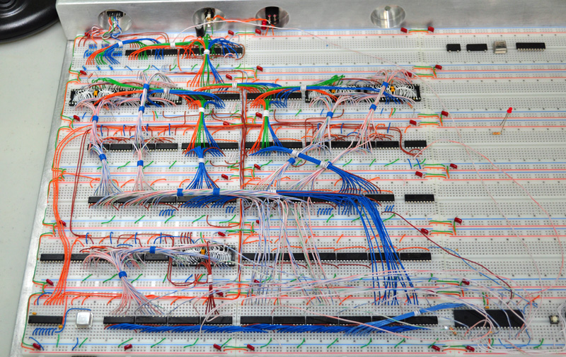
Dual Buffers, Sync Generator, and the Video Memory Switch.
This proves out the new design, so now I can start work on the new Graphics Generator.
As a test, I made a basic demo that rotates and changes the color of a moving torus.
It uses the torus as a "brush" to paint lines that look like twisted rainbow strings.
I call this effect "String Theory"...
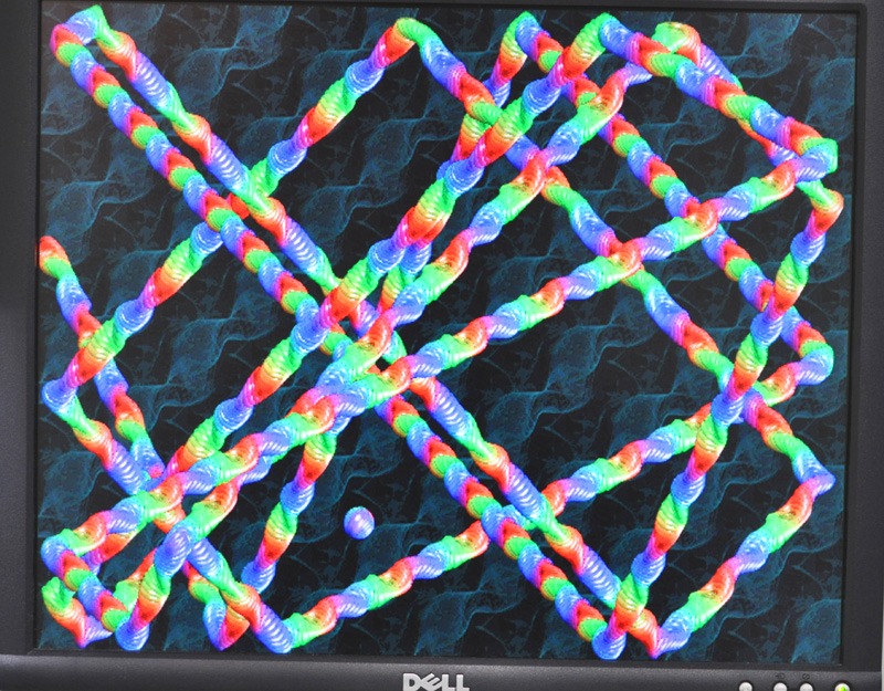
Everything looks good with 4096 colors and high resolution.
Here is a video of the demo drawing the string...
https://www.youtube.com/watch?v=vo0ra2RL-T4
The demo is only a few lines of assembly, and limited since graphics are stored in the small uC memory.
Once I have 4 Megs of Graphics Memory installed along with the Blitter, the power will be endless!
My next mod will be a few ICs to offer multiple video modes (8 new modes).
A smaller screen resolution mode such as 320x480 might be good for faster demo effects.
Here are some of the modes that will be available (all have 4096 colors)...
640x480, 640x240, 640x160, 640x120
320x480, 320x240, 320x160, 320x120
160x480, 160x240, 160x160, 160,120
And yes, like the Amiga, the vertical mode can be switched on the fly for multiple modes per screen.
So far, so good!
I will post in more detail when I can. The real World has kept me busy lately.
Cheers!
Radical Brad
Both buffers are connected, and the 60 line IO switch is doing its job nicely.
Here is the state of the board now. A lot of wiring is not routed nicely yet, so please excuse the mess!...
Dual Buffers, Sync Generator, and the Video Memory Switch.
This proves out the new design, so now I can start work on the new Graphics Generator.
As a test, I made a basic demo that rotates and changes the color of a moving torus.
It uses the torus as a "brush" to paint lines that look like twisted rainbow strings.
I call this effect "String Theory"...
Everything looks good with 4096 colors and high resolution.
Here is a video of the demo drawing the string...
https://www.youtube.com/watch?v=vo0ra2RL-T4
The demo is only a few lines of assembly, and limited since graphics are stored in the small uC memory.
Once I have 4 Megs of Graphics Memory installed along with the Blitter, the power will be endless!
My next mod will be a few ICs to offer multiple video modes (8 new modes).
A smaller screen resolution mode such as 320x480 might be good for faster demo effects.
Here are some of the modes that will be available (all have 4096 colors)...
640x480, 640x240, 640x160, 640x120
320x480, 320x240, 320x160, 320x120
160x480, 160x240, 160x160, 160,120
And yes, like the Amiga, the vertical mode can be switched on the fly for multiple modes per screen.
So far, so good!
I will post in more detail when I can. The real World has kept me busy lately.
Cheers!
Radical Brad
-
Oneironaut
- Posts: 734
- Joined: 25 May 2015
- Location: Gillies, Ontario, Canada
- Contact:
Re: Vulcan-74 - A 6502 Powered Retro MegaProject
Having hit the razor's edge when it comes to what can be done on a breadboard now, I have started to consider my PCB options.
I want something as hand-made as possible, so I am exploring some really bizarre possibilities here....
Option One - Just get a real PCB made.
Expensive (need a 16" x 16" board), and not so cool.
Performance will be good.
Option Two - Point to Point on perforated board.
This will be a fun amount of work, and look cool.
The problem is with debugging and chip replacement.
Option Three - CNC routed massive PCB
At work, I have access to some nice 5 axis CNC equipment.
This would be a cool DIY approach, and performance would be good.
Option Four - Hand wired clear PCB!
Yeah... I like this one since it is both difficult and unique.
This one needs a bit more explanation...
The idea is to take a large piece of 3/16" clear Lexan and hand drill all of the holes.
Once all 50 million holes are drilled, IC are placed onto the board.
The VCC and GND leads would then be slightly bent towards sets of copper rails.
Copper VCC and GND rails would be made by straightening stripped house wire for the copper.
These rails would also be soldered into a crossing pattern to form a huge GND and VCC matrix.
Clock lines would be routed on the bottom as well, and all buss wires on the top.
I think this would be the best design for combating capacitance as well as ground bounce.
My poor breadboard is taking on a lot of capacitance right now, so this issue is on my mind.
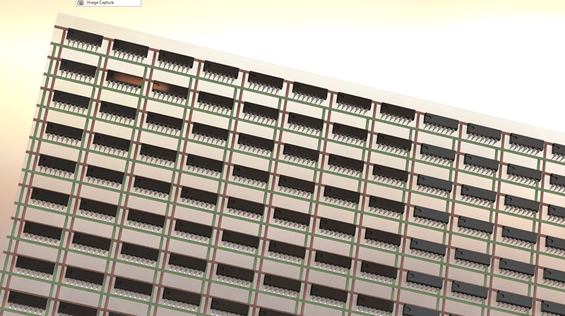
Here are some SolidWorks renders of what I am considering for my board...
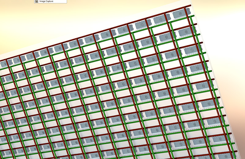
There would be two clear boards, each with 150+ ICs.
The GND and VCC Matrix would be very extensive, crossing every single IC.
ICs are soldered directly to the huge GND and VCC Matrix.
Wiring would by tidy, and ICs could be easily replaced if required.
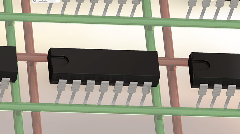
The Power Matrix is #12 AWG copper wire (house wire)
I am going to make two boards - one for Video and one for Sound.
This works out nicely since both have about 150 ICs.
The bus between them is just 10 or so wires (8 bit data, and control).
This board design should be highly immune to ground bounce, and other issues.
Unless I have shocked myself too many times, this may be "better" than a standard PCB.
Adding decoupling caps would also be easy with the large copper bars.
I have some time to consider my board though, as my GFX Generator is not even built yet.
Brad
I want something as hand-made as possible, so I am exploring some really bizarre possibilities here....
Option One - Just get a real PCB made.
Expensive (need a 16" x 16" board), and not so cool.
Performance will be good.
Option Two - Point to Point on perforated board.
This will be a fun amount of work, and look cool.
The problem is with debugging and chip replacement.
Option Three - CNC routed massive PCB
At work, I have access to some nice 5 axis CNC equipment.
This would be a cool DIY approach, and performance would be good.
Option Four - Hand wired clear PCB!
Yeah... I like this one since it is both difficult and unique.
This one needs a bit more explanation...
The idea is to take a large piece of 3/16" clear Lexan and hand drill all of the holes.
Once all 50 million holes are drilled, IC are placed onto the board.
The VCC and GND leads would then be slightly bent towards sets of copper rails.
Copper VCC and GND rails would be made by straightening stripped house wire for the copper.
These rails would also be soldered into a crossing pattern to form a huge GND and VCC matrix.
Clock lines would be routed on the bottom as well, and all buss wires on the top.
I think this would be the best design for combating capacitance as well as ground bounce.
My poor breadboard is taking on a lot of capacitance right now, so this issue is on my mind.
Here are some SolidWorks renders of what I am considering for my board...
There would be two clear boards, each with 150+ ICs.
The GND and VCC Matrix would be very extensive, crossing every single IC.
ICs are soldered directly to the huge GND and VCC Matrix.
Wiring would by tidy, and ICs could be easily replaced if required.
The Power Matrix is #12 AWG copper wire (house wire)
I am going to make two boards - one for Video and one for Sound.
This works out nicely since both have about 150 ICs.
The bus between them is just 10 or so wires (8 bit data, and control).
This board design should be highly immune to ground bounce, and other issues.
Unless I have shocked myself too many times, this may be "better" than a standard PCB.
Adding decoupling caps would also be easy with the large copper bars.
I have some time to consider my board though, as my GFX Generator is not even built yet.
Brad
-
GARTHWILSON

- Forum Moderator
- Posts: 8775
- Joined: 30 Aug 2002
- Location: Southern California
- Contact:
Re: Vulcan-74 - A 6502 Powered Retro MegaProject
Wire-wrap works well for these reasons:
There are pre-made solder-type breadboards available that already have power and ground strips going down between the ICs' rows of pins, like:
All these boards are pretty expensive, but cheaper than a raft of solderless breadboards. The latter set is intended to be soldered, not wire-wrapped.
If you do your own bus wire, note that the wire size has very little effect on inductance, only resistance which is pretty minimal for CMOS circuits without going to 12 AWG wire. #24 or 26 should be easier to build with, and the performance should be indistinguishable with such a nice grid of them.
If you use a 3/16"-thick clear board like plexiglass, the pins on most ICs and soldertail sockets won't be long enough to get through the holes.
- You can get the sockets shoulder-to-shoulder, so everything is closer together and connections are shorter.
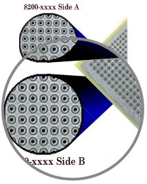
- You can get power and ground planes on the perfboards, like Twin Industries' 8100-series boards with one plane or their 8200-series boards with a plane on each side. You would solder a short connection from each ground pin to the ground plane around it and a chip capacitor from each power pin to the ground plane around it (that's the easy part), and if you have a power plane too (here comes the harder part), you put a strand of wire through the hole before putting the socket in, and solder the top of it to the power plane around it. The bottom of the wire can be cut flush with the board. Solder the socket pin into the thru-plated hole.
- You won't be breaking previously placed wires by moving them to access pin to solder to, since the wires just get wrapped, not soldered.
- You won't get the capacitance between strips that you're getting on solderless breadboards.
- Modification is not too difficult (unlike a PCB or soldered wires).
There are pre-made solder-type breadboards available that already have power and ground strips going down between the ICs' rows of pins, like:
- Vector's 4616 6U VME size,
- or their 4615 (same size),
- or this one from Vero,
- or this bigger 6U-VME-sized one,
- or this smaller one from Twin Industries.
All these boards are pretty expensive, but cheaper than a raft of solderless breadboards. The latter set is intended to be soldered, not wire-wrapped.
If you do your own bus wire, note that the wire size has very little effect on inductance, only resistance which is pretty minimal for CMOS circuits without going to 12 AWG wire. #24 or 26 should be easier to build with, and the performance should be indistinguishable with such a nice grid of them.
If you use a 3/16"-thick clear board like plexiglass, the pins on most ICs and soldertail sockets won't be long enough to get through the holes.
http://WilsonMinesCo.com/ lots of 6502 resources
The "second front page" is http://wilsonminesco.com/links.html .
What's an additional VIA among friends, anyhow?
The "second front page" is http://wilsonminesco.com/links.html .
What's an additional VIA among friends, anyhow?

Re: Vulcan-74 - A 6502 Powered Retro MegaProject
Oneironaut wrote:
At work, I have access to some nice 5 axis CNC equipment.
any chance of "tricking" your CNC into welding wires (or enameled wires) to a PCB ?
http://www.wirelaid.com/
-
Oneironaut
- Posts: 734
- Joined: 25 May 2015
- Location: Gillies, Ontario, Canada
- Contact:
Re: Vulcan-74 - A 6502 Powered Retro MegaProject
Garth,
I did research the wirewrap option as well.
Like you said, GND / VCC would still need o be "super-sized" for my project, so it might as well roll my own grid.
I only paid $6.00 for each breadboard, and my aluminum back is worth about $20. So, $308.00 all in.
Considering even $3.00 per wire wrap socket, and the thin wire, I would guess $1000 easy for wire wrap.
The clear DIY PCB on the other hand would be less than $50, including the copper rails.
Plus, the DIY PCB adds that... "WTF?!, that dude is insane" factor, which I do enjoy!
TTL,
The CNC will not do any welding, but I am looking a somehow using the 30 watt laser engraver to help out.
Might be able to do "pilot" holes with the laser, so drilling is a little bit easier.
I will be tasked with hand drilling about 9600 holes in the lexan if I do this method.
Brad
Re: Vulcan-74 - A 6502 Powered Retro MegaProject
Oneironaut wrote:
I will be tasked with hand drilling about 9600 holes in the lexan if I do this method.
Hey, many years ago I had a nice project at work: drilling holes into bones by using a pulsed Erbium_YAG laser.
(5W, if I remember correctly.) Evaporating PCB material probably would give a similar smell.
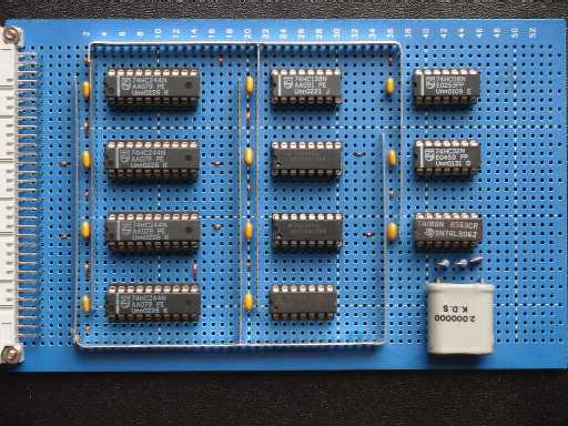
About the power supply matrix:
When forum member Andrew Holme had built his first TTL CPU, he had made creative use of sheet metal for the power supply:

Re: Vulcan-74 - A 6502 Powered Retro MegaProject
ttlworks wrote:
Oneironaut wrote:
At work, I have access to some nice 5 axis CNC equipment.
any chance of "tricking" your CNC into welding wires (or enameled wires) to a PCB ?
http://www.wirelaid.com/
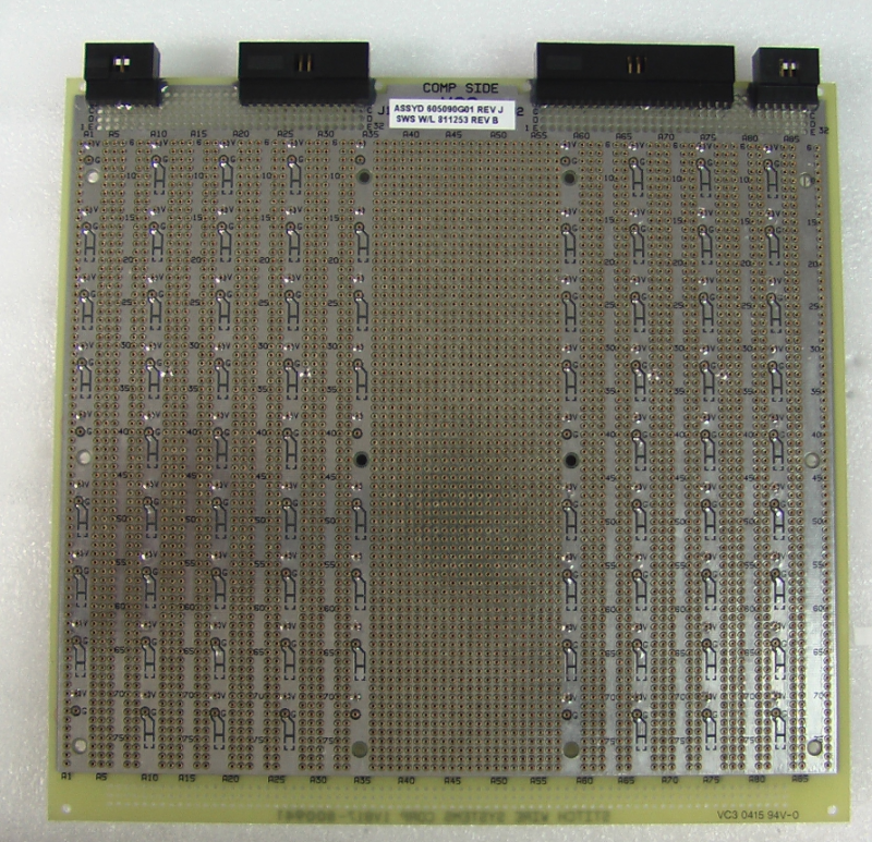
I have tried to make a photo of an old pcb I still have:
I can't remember how many "copper trace layers" on (each) side of the pcb were allowed. But AFAIR there was never a routing problem.
Sadly this service died down in the 90s. Our supplier vanishes 5 or so years later. Google says this technology is now covered by Hitachi.
-
GARTHWILSON
- Forum Moderator
- Posts: 8775
- Joined: 30 Aug 2002
- Location: Southern California
- Contact:
Re: Vulcan-74 - A 6502 Powered Retro MegaProject
GaBuZoMeu, that reminds me of wire stitch. As I remember (although I never used it):
In ttlworks' photo of Andrew Holme's use of narrow strips of sheet metal, for best performance you would still want wires going across from ground to ground and power to power between ICs.
Uh, I'm not sure where you got that idea. What I was saying is that wire size has very little effect on inductance. You can use the wire inductance calculator at http://www.eeweb.com/toolbox/wire-inductance . An inch of 30 AWG wire (WW wire) has 26.7nH of inductance. The same length of 12 AWG wire has 16.2nH. IOW, going to eight times the diameter and 64 times the cross-sectional area only reduced the inductance by about 39%. OTOH, using proto board with planes on both sides (one for power, one for ground) like Twin Industries' 8200 series
gives essentially zero inductance in the power and ground connections, from what I gathered from Dr. Howard Johnson's articles. (The IC sockets and leadframes will still have some inductance of course, and we could wish the 7400 series started out decades ago with power and ground on the middle pins, closest to the die.
Aside from the wire-stitch thing, everything I've been writing here is in the 6502 primer.
You do like to do things your own way though, which is fine when you're doing it for yourself. I myself have had some great accomplishments sometimes from being stubborn. I've had some of these moments at work over the years:
- you start with something like a perfboard but with power and ground strips going down between the ICs' pin rows
up to 12U by 400mm! - there are places to solder chip bypass capacitors at every IC
- the holes are plated through
- they put a screw-machine pin socket in every hole you'll need an IC pin
- they use machines to solder enameled wire, then lay it down against the board and lacquer it to the board so you can have lots of layers yet a thin outcome.
In ttlworks' photo of Andrew Holme's use of narrow strips of sheet metal, for best performance you would still want wires going across from ground to ground and power to power between ICs.
Quote:
Like you said, GND / VCC would still need o be "super-sized" for my project,
gives essentially zero inductance in the power and ground connections, from what I gathered from Dr. Howard Johnson's articles. (The IC sockets and leadframes will still have some inductance of course, and we could wish the 7400 series started out decades ago with power and ground on the middle pins, closest to the die.
Aside from the wire-stitch thing, everything I've been writing here is in the 6502 primer.
You do like to do things your own way though, which is fine when you're doing it for yourself. I myself have had some great accomplishments sometimes from being stubborn. I've had some of these moments at work over the years:
http://WilsonMinesCo.com/ lots of 6502 resources
The "second front page" is http://wilsonminesco.com/links.html .
What's an additional VIA among friends, anyhow?
The "second front page" is http://wilsonminesco.com/links.html .
What's an additional VIA among friends, anyhow?