Page 3 of 3
Re: Prototype Construction Tips
Posted: Thu Nov 15, 2018 7:33 pm
by floobydust
I've been using the Aires ZIF sockets for years. I simply stack a couple extra 28-pin DIP sockets into the PCB's mounted DIP socket and then plug the ZIF socket into it. This elevates the ZIF socket above the PCB by roughly a 1/2-inch, so it clears other parts and/or connectors.
https://www.mouser.com/datasheet/2/35/1 ... 337360.pdf
They are a bit pricey, depending on your POV... but they have come down in price over the past few years. Of course, once I'm done with software changes, I pull the ZIF socket assembly and just go back to a standard EEPROM directly into the PCB socket.
Re: Prototype Construction Tips
Posted: Thu Nov 15, 2018 9:00 pm
by GARTHWILSON
I inherited a few of those boards, but have only used them for tiny stuff. What I like about that kind is that you can set how long you want each trace—although I've always wondered if there was an easy way to cut lots of them like you would need to to make a board like you show here.
I've used scores of Radio Shack
276-170 solder-type breadboards over the years for analog stuff:
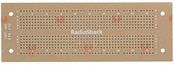
It duplicates the pattern on the solderless breadboards they've sold.
Some nicer options I discovered in recent years are shown at
http://www.busboard.com/KIT-BB1660-SB1660 . Here's one of them:
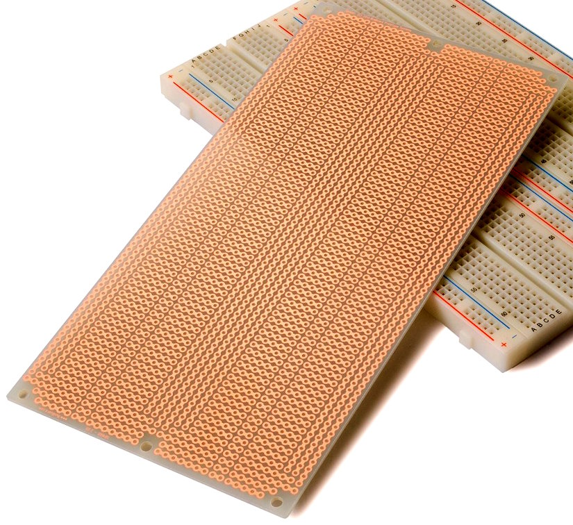
(These are from the bottom of the "Custom PC Boards"
section of my 6502 primer.)
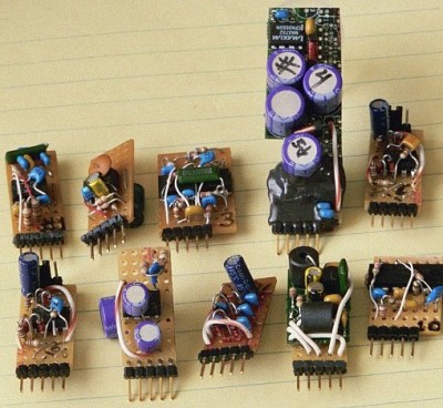
Reusable modules are great. Goals for a home-made computer tend to quickly become too lofty to carry them out in your lifetime—or change faster than you can build. It helps to have various sections ready-made (hence my memory modules, and other tiny ones I hope to offer). For my own use, I have a lot of reusable tiny analog modules so I don't have to keep re-building them for every breadboard. This is about one-third of them:
Re: Prototype Construction Tips
Posted: Fri Nov 16, 2018 3:57 pm
by BillO
I've been using (for 40 years now) Miller model 103 wire strippers to strip WW (and other) wire. Seem to last forever.
The WW wire I got from ebay seems fine, but it was so long ago I can no longer look up who I bought it from.
Reusable modules are great. Goals for a home-made computer tend to quickly become too lofty to carry them out in your lifetime—or change faster than you can build. It helps to have various sections ready-made (hence my memory modules, and other tiny ones I hope to offer). For my own use, I have a lot of reusable tiny analog modules so I don't have to keep re-building them for every breadboard. This is about one-third of them:
This is a great idea and one I have used a lot, especially in microcontroller work. Saves so much time, effort and mess. Works with digital stuff too.
Re: Prototype Construction Tips
Posted: Sat Nov 17, 2018 1:49 am
by BigDumbDinosaur
I had not seen "EJECT-A-DIP" (
28-pin,
40-pin) before. Neat, so it's a machine-tooled socket with additional locking tabs that can also eject the chip.
Furthermore, it can be safely plugged into a "wipe"-style DIP socket. So it could be used as a ZIF in a unit undergoing test and then removed and set aside when no longer needed.
The datasheet says it is recommended for high-vibration environments.
I'm hoping that I won't need that feature around here.

As far as I know, we're not in a seismically-active part of the world.
Re: Prototype Construction Tips
Posted: Wed Dec 05, 2018 8:35 am
by GARTHWILSON
Here's another, for pin headers of .025" square posts with a standard .230" length at one end and longer pins on the other end. I used these for the mezzanine on my workbench computer, both on the mezzanine shown here (before there was anything on it), and down on the main board where the long end of the pins were used for wire-wrapping (between the 40-pin DIP sockets) and I soldered a socket to the shorter end:
The second row is near the right edge of the above picture, and blurry. This following picture shows it slightly better, behind the blue trimmer which is for adjusting the LCD viewing angle:
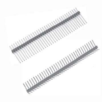
Here are some Mouser links to single-row ones:
.235" at one end, .410" at the other end
.235" at one end, .610" at the other end
.235" at one end, .910" at the other end
They're kind of expensive, but if you're only doing one-off projects, the time they save you is well worth their price.
You can also get dual-row ones which are good for plugging IDCs onto. This picture shows a couple with red insulators (after the same mezzanine had some circuitry built onto it:
Re: Prototype Construction Tips
Posted: Wed Dec 05, 2018 2:13 pm
by cbmeeks
Reusable modules are great. Goals for a home-made computer tend to quickly become too lofty to carry them out in your lifetime—or change faster than you can build. It helps to have various sections ready-made (hence my memory modules, and other tiny ones I hope to offer). For my own use, I have a lot of reusable tiny analog modules so I don't have to keep re-building them for every breadboard. This is about one-third of them:
That's a great idea. "Shields" before we called them shields.
Re: Prototype Construction Tips
Posted: Fri Dec 07, 2018 2:39 am
by LIV2
If it turns out that the EJECT-A-DIP is mechanically compatible with a DIP plug, that could be a nice upgrade to keep the DIP plug locked in.
I'm using a DIP plug with the Eject-a-DIP and found that the DIP plug is a little too thick for the socket, I filed some notches in my plug so it'd fit and it works well
Re: Prototype Construction Tips
Posted: Mon Dec 10, 2018 4:16 pm
by BigEd
Anyone gone so far as to use the book-of-pages approach to multiboard wirewrapped prototypes, as used by the Amiga team?

(Images from
this page, ultimately from the 1992
History of The Amiga documentary "created on an Amiga 2000")
Re: Prototype Construction Tips
Posted: Mon Dec 10, 2018 5:13 pm
by Chromatix
As also used by Seymour Cray for commercial products!
Re: Prototype Construction Tips
Posted: Mon Dec 10, 2018 5:51 pm
by Dr Jefyll
Daryl's
SBC4 is another instance of the book-of-pages approach. ( Probably that's where Seymour got the idea!

)
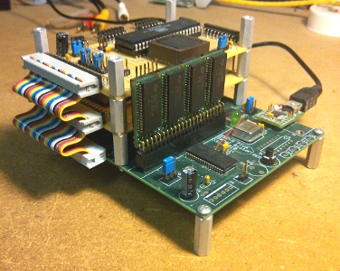
- MM2a.jpg (72.46 KiB) Viewed 2204 times
Seriously, I like the fact that the "book" can be spread open to
grant access to both sides of any individual board.

Furthermore, ribbon cable + IDC's are easier to design and build with, compared with connectors soldered into a rigid backplane. Cheaper, too.
(Of course, it's strongly recommended that ground lines be interspersed with the signal lines, regardless of whether your "backplane" is flexible or rigid.)
-- Jeff
Re: Prototype Construction Tips
Posted: Mon Dec 10, 2018 9:05 pm
by BigEd
That's a nice machine! The
steckschwein is not dissimilar:
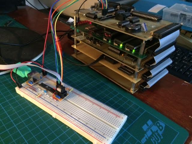