Dr Jefyll wrote:
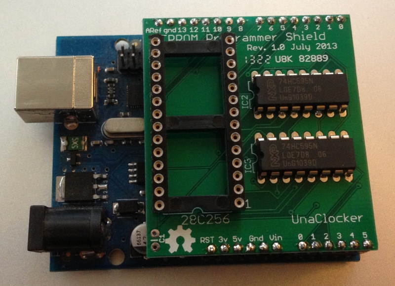
The "funny" problem you describe makes me wonder about the power supply. I don't see any supply bypass capacitors -- do you have them hidden on the other side of the board? Two possible ways to proceed:
- 'scope the supply to see if you can observe a brief sag as programming commences; or...
- just add some capacitance and see if the symptom disappears. I'd suggest a generous electrolytic (10-100 uF maybe?) and also, located physically close to the EEPROM socket, a .1 or .01 uF with leads kept reasonably short.
Looks like a good call, Jeff. I have noted in the past that when an EPROM goes from the standby mode to active a noticeable power supply transient can occur. I quote from the AMD data sheet for their EPROMs:
- During the switch between active and standby conditions, transient current peaks are produced on the rising and falling edges of Chip Enable. The magnitude of these transient current peaks is dependent on the output capacitance loading of the device. At a minimum, a 0.1 μF ceramic capacitor (high frequency, low inherent inductance) should be used on each device between VCC and VSS to minimize transient effects. In addition, to overcome the voltage drop caused by the inductive effects of the printed circuit board traces on EPROM arrays, a 4.7 μF bulk electrolytic capacitor should be used between VCC and VSS for each eight devices. The location of the capacitor should be close to where the power supply is connected to the array.
Although AMD's data sheet is referring to EPROMs (especially an array of them), EEPROMs are behaviorly similar and could misbehave if a power supply sag occurs at the chip.