Page 3 of 11
Re: HDL Implementation of Video Generator Test for 16-bit PV
Posted: Wed Sep 26, 2012 3:04 pm
by ElEctric_EyE
OK Finally got it working! Closeup of the upperleft portion of the monitor. This is ramping RGB from high to low. Noise issue is gone as well.

Re: HDL Implementation of Video Generator Test for 16-bit PV
Posted: Wed Sep 26, 2012 4:12 pm
by ElEctric_EyE
External control of the PROM select and FPGA /Program works as expected. 2 different patterns were programmed and selected successfully. Good news is PROM 1 & 2 designations on the board matches up with ISE. When ISE initiates the JTAG scan it shows the leftmost PROM (1), the middle PROM (2) and the FPGA on the right.
I think it's time to solder in the SyncRAM and try to come up with some simple HDL to try reading from it.
Re: HDL Implementation of Video Generator Test for 16-bit PV
Posted: Wed Sep 26, 2012 4:43 pm
by BigDumbDinosaur
OK Finally got it working! Closeup of the upperleft portion of the monitor. This is ramping RGB from high to low. Noise issue is gone as well.
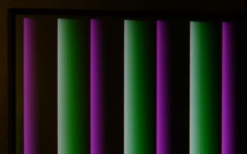
Looks like designer vertical window blinds.  Good job!
Re: HDL Implementation of Video Generator Test for 16-bit PV
Posted: Wed Sep 26, 2012 5:10 pm
by BigEd
Well done!
Re: HDL Implementation of Video Generator Test for 16-bit PV
Posted: Wed Sep 26, 2012 6:26 pm
by ElEctric_EyE
Guys, thanks! Very excited here. I soldered in the .65mm SyncRAM. Overdid it with the solder and used braid to get excess off. I like this technique! Will use it from now on. PVB powers up and runs still and no smoke...
Now I've been busy with some code and cannot use a testbench since there's no way to simulate the RAM. But I have made a successsful symbol with all the I/O's present, so the ISE tool must think it knows what I want to do. I've tried to approach it logically. Here goes:
Code: Select all
module SRAMif( output reg [20:0] SRA = 0,
					output reg WEn = 1,
					output reg SRCLK = 0,
					output reg SRCS = 0,
					input [15:0] SRD,
					output reg [4:0] Red_data,
					output reg [5:0] Green_data,
					output reg [4:0] Blue_data,
					input clk50,
					input pclk,
					input hstart,
					input vstart,
					input hblank
					);
reg [15:0] SRDtemp;
reg countflag;

always @(posedge clk50)
		SRCLK <= ~SRCLK;		//pixel clk is SyncRAM clk

always @(posedge clk50)
	if ( hstart & vstart )	//reset address counter at top left of screen
		SRA <= 0;

always @(posedge clk50)
   if ( pclk )
      if ( hstart )
         countflag <= 1;	//countflag active in display area
      else if ( hblank )
         countflag <= 0;

always @(posedge clk50)
	if ( countflag )
		SRA <= SRA +1;			//increment RAM address counter

always @(posedge clk50)
	if ( pclk & countflag )
			SRDtemp <= SRD;	//latch incoming data

always @(posedge clk50)
	if ( pclk & countflag )
		begin
			Red_data <= SRDtemp [15:11];		//outgoing data to videoDAC
			Green_data <= SRDtemp [10:5];
			Blue_data <= SRDtemp [4:0];
		end

endmodule
Re: HDL Implementation of Video Generator Test for 16-bit PV
Posted: Wed Sep 26, 2012 6:43 pm
by Arlet
Guys, thanks! Very excited here. I soldered in the .65mm SyncRAM. Overdid it with the solder and used braid to get excess off. I like this technique!
If you use too much solder, sometimes little blobs get stuck behind the pins. These can be nasty, as they are hard to see, and since they're only barely touching the pins, they don't always melt when you touch the pins with the iron. If that happens, you can fix it by adding some extra solder, and then use one of those hand held solder suckers to get it out. That's why I started to use the other technique I mentioned: load up a piece of braid, and use that as a brush to "paint" the solder on the pins. This avoids the problem in the first place.
In any case, try not to use really dry braid. If it works too well, it sometimes leaves too little on the pin. Instead, if it gets saturated, only cut off the end, but leave the half-saturated part. It's a matter of trial and error and experience to see how much you need.
Re: HDL Implementation of Video Generator Test for 16-bit PV
Posted: Wed Sep 26, 2012 7:19 pm
by ElEctric_EyE
...In any case, try not to use really dry braid. If it works too well, it sometimes leaves too little on the pin. Instead, if it gets saturated, only cut off the end, but leave the half-saturated part. It's a matter of trial and error and experience to see how much you need.
Yeah, I used dry braid and it really took up the solder. I went back over the pins with the solder tip. We'll see if I was successful...
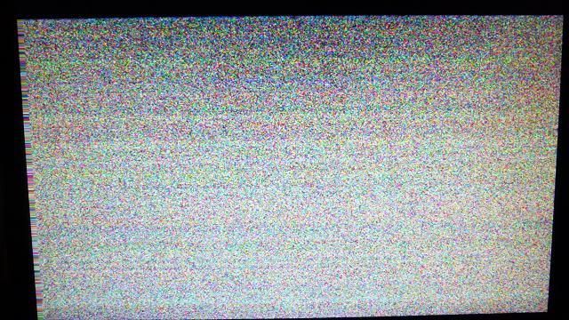
Last post with code passed syntax check and was able to make a symbol, but it did not synthesize. SRA was a reserved name, so had to change it, also SRCS was wrong value. I did not have the SyncRAM address outputs registered like I did with the databus outputs and got a multiple driver error. So I fixed it, and it passes sythesis. I tried it out. Getting totally random pixels all the time. Timing not right. But it's something!
Code: Select all
module SRAMif( output reg [20:0] SRAddr = 0,					//SyncRAM address bus
					output reg WEn = 1,			//SyncRAM R/W, always read
					output reg SRCLK = 0,			//SyncRAM clock
					output reg SRCS = 1,			//SyncRAM chip select
					input [15:0] SRD,				//SyncRAM databus
					output reg [4:0] Red_data,		//
					output reg [5:0] Green_data,		//videoDAC databus, always write
					output reg [4:0] Blue_data,		//
					input clk50,				//50MHz main clock
					input pclk,					//25MHz pixel clock
					input hstart,
					input vstart,
					input hblank
					);
reg [20:0] SRAddrtemp;
reg [15:0] SRDtemp;
reg countflag;

always @(posedge clk50)
		SRCLK <= ~SRCLK;		//pixel clk is SyncRAM clk

always @(posedge clk50)
   if ( pclk )
      if ( hstart )
         countflag <= 1;	//countflag active in display area
      else if ( hblank )
         countflag <= 0;

always @(posedge clk50)
	if ( hstart & vstart )	//reset address counter at top left of screen
		SRAddrtemp <= 0;
	else if ( countflag )
		SRAddrtemp <= SRAddrtemp +1;			//increment RAM address counter

always @(posedge clk50)
	if ( pclk & countflag )
			SRDtemp <= SRD;	//latch incoming data

always @(posedge clk50)
	if ( pclk & countflag )
		begin
			Red_data <= SRDtemp [15:11];		//outgoing data to videoDAC
			Green_data <= SRDtemp [10:5];
			Blue_data <= SRDtemp [4:0];
		end

always @(posedge clk50)
	if ( pclk & countflag )
		SRAddr <= SRAddrtemp;	//outgoing address

endmodule
Re: HDL Implementation of Video Generator Test for 16-bit PV
Posted: Wed Sep 26, 2012 7:23 pm
by Arlet
Are the pixels stable, or are they flickering ?
Re: HDL Implementation of Video Generator Test for 16-bit PV
Posted: Wed Sep 26, 2012 7:25 pm
by ElEctric_EyE
Always changing, like my address counter is not being reset.
EDIT: I will go back to the simulator and see how your HVSync module works.
Re: HDL Implementation of Video Generator Test for 16-bit PV
Posted: Wed Sep 26, 2012 7:34 pm
by Arlet
Here's a
verilog model of the RAM
Re: HDL Implementation of Video Generator Test for 16-bit PV
Posted: Wed Sep 26, 2012 8:08 pm
by ElEctric_EyE
Thanks for looking that up. I'm sure i will need that in time, but now I know my problem is that the RAM counter is not being reset. My logic for resetting it using hstart and vstart is wrong. I must determine how to tell it the last pixel has been displayed. Maybe I could generate this signal from within your vga.v HVSynv module?
Re: HDL Implementation of Video Generator Test for 16-bit PV
Posted: Wed Sep 26, 2012 10:16 pm
by Arlet
Here's a problem:
Code: Select all
if ( hstart & vstart ) //reset address counter at top left of screen
The hstart and vstart pulses don't happen at the same time. Try resetting the address counter just based on vstart. The vstart signal comes early, so you can prepare the data path. At hstart, you start incrementing.
You'll still have artifacts because the code doesn't compensate for all the pipeline delays, but at least you should have a stable picture.
Re: HDL Implementation of Video Generator Test for 16-bit PV
Posted: Thu Sep 27, 2012 12:06 am
by ElEctric_EyE
...You'll still have artifacts because the code doesn't compensate for all the pipeline delays, but at least you should have a stable picture.
Arlet, thanks for your tip.
I'm aiming for a stable pixel generation (i.e. data from a fast
read-only memory (in my
initial test), non-FPGA Block Memory, but similar) and should be able to achieve it at such a low pixel clock (25 MHz, 40ns access time) without even looking at timing diag's. Hopefully this pass-thru synchronous RAM has a 6.5ns delay, not pipelined like the other versions of this Synchronous RAM.
Re: HDL Implementation of Video Generator Test for 16-bit PV
Posted: Thu Sep 27, 2012 12:36 am
by MichaelM
EEyE:
This comment is not going to help, but I suggest that you use a single clock for the SRAM. Your comment on the following code says it, so I would recommed using pclk as the clock source for the SRAM.
Code: Select all
always @(posedge clk50)
      SRCLK <= ~SRCLK;      //pixel clk is SyncRAM clk
However, instead of using an assignment statement (and its potential path delays), I would suggest clocking the SRAM in the following manner:
Code: Select all
always @(posedge clk50)
      SRCLK <= ~pclk;      //pixel clk is SyncRAM clk
This will allow pclk == 1 to function as the enable for input FFs in the IOBs, which appears to be already included in your SRAM interface module.
====================================================
Thinking on this a bit more, I suggest that you need to look at the path delays in the IOB relative to the SRCLK and pclk. My understanding of the signal timing means that your use of the same phase of the clock (pclk and SRCLK should be in-phase) means that you are sampling the data in the middle of the cycle instead at the end of the cycle. I expect that the data may not be stable at that point, or if it is, you have not applied a NO_DELAY attribute on the input buffer of the FPGA. In either case, the data is clearly not stable, unless of course the SRAMs are not initialized.
The changes I suggested above should alleviate this timing issue.
Re: HDL Implementation of Video Generator Test for 16-bit PV
Posted: Thu Sep 27, 2012 12:08 pm
by ElEctric_EyE
That does help. pclk and SRCLK need to be the same. I will just rename 1 and adjust the ucf accordingly. But I think what's happening presently is that with a 2MB RAM and 640x480=311040 pixels, the data being written to the videoDACs is overlapping on the display, since my address counter does not have the correct logic to reset to 0 at the end of the last pixel. That's enough memory for 6.7 displays.
Hopefully will have time tonight to try yours and Arlet's suggestions. Thanks!