Page 2 of 3
Re: Verilog code to interface an FPGA with a real WDC65C816S
Posted: Mon Apr 22, 2019 2:40 am
by Dr Jefyll
beholdnec, if you post a photo of your layout then that might be revealing. Indeed, there might be opportunities for significant improvements without much effort. (BTW on this forum you're allowed to attach images with your posts.)
cheers,
Jeff
Re: Verilog code to interface an FPGA with a real WDC65C816S
Posted: Mon Apr 22, 2019 3:45 am
by beholdnec
390.625GHz? Er...390.625kHz.

Yep, that's what I meant!

Sorry, it's the weekend and my brain is asleep.
I suppose I might as well show off the project. Attached is a photo. Please don't laugh.
As I've mentioned, the FPGA is able to detect the FFFC,FFFD bootup sequence and run a program made of all NOP's (0xEA). Attached is a capture of the A0 line when running NOP's (it should toggle every cycle). The result looks... more like a sawblade than a digital signal. The "0" part is -0.1 to 0.3 V. The "1" part is 2.59 to 3.20 V. At a 3.3V power supply, this is barely within tolerances. Something should probably be done to improve it.
It might be important to note that the Pynq-Z1 board has 200-ohm safety resistors on almost all of its digital I/O pins. There are 6 pins available without resistors, but I don't want to use those pins unless I absolutely have to.
Re: Verilog code to interface an FPGA with a real WDC65C816S
Posted: Mon Apr 22, 2019 6:07 am
by GaBuZoMeu
Oh oh - I cannot find any capacitor on your breadboard !?
This is very necessary : place a 100 nF (0.1 µF) capacitor (ceramic or film) between Vdd (pin 8 ) and GND. The cap's pin should be next to pin 8 then the (shortest available) wire to Vdd. There another 0.1µF should sit directly between Vdd and GND. I would add another one (this time 10µ tantalum or ceramic) where you power the breadboard (black & white wires).
Second: provide a shorter (additional) wire between GND (pin 21) and GND - best a wire to the other pin of that C that is next to pin 8.
Re: Verilog code to interface an FPGA with a real WDC65C816S
Posted: Mon Apr 22, 2019 6:50 am
by GARTHWILSON
Yes, and this is where I was saying there should be a capacitor straddling the IC itself, with the shortest possible connection from the VDD pin to the Vss pin. Connection length adds inductance, something you definitely don't want here. Capacitor leads will have about 18 nanoHenries of inductance per inch of length.
Re: Verilog code to interface an FPGA with a real WDC65C816S
Posted: Mon Apr 22, 2019 6:24 pm
by Dr Jefyll
there should be a capacitor straddling the IC itself, with the shortest possible connection from the VDD pin to the Vss pin
Right. Here's a photo to illustrate. It's not on a breadboard (I don't own any) but it'll give you the idea just the same. The soldered version is preferred, though perhaps less convenient.
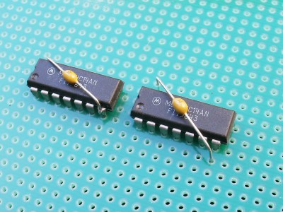
- bypass capacitors.JPG (43.4 KiB) Viewed 2127 times
Attached is a capture of the A0 line when runnin.g NOP's (it should toggle every cycle).
Actually not. NOP (opcode $EA) is a one-byte instruction that takes two cycles to execute. Thus you can expect A0 to toggle every other cycle. To see toggling every cycle, use a
two-byte instruction that takes two cycles to execute, such as LDA #. The opcode is $A9, and if you like you can use $A9 as the operand, too -- that way there's only one value to apply tothe data bus.

cheers
Jeff
Re: Verilog code to interface an FPGA with a real WDC65C816S
Posted: Tue Apr 23, 2019 2:47 am
by beholdnec
Thank you all for the advice! Why, yes, I am a bit of a novice... I knew it was good to have caps near a chip but I didn't have any on hand, and I guessed that it wasn't terribly important.
Now I have caps on my board, and the signal is much cleaner.
Unfortunately the data lines seem to be transmitting late. That is, the FPGA thinks it sends the bytes 00, 06 when the 65816 requests the reset address FFFC,FFFD, however, the 65816 then starts executing from address 00000a9 and FPGA reads nonsensical data from the 65816. I suspect this is a timing issue, where the signals fail to meet setup and hold times. Attached is a trace from the FPGA.
Re: Verilog code to interface an FPGA with a real WDC65C816S
Posted: Tue Apr 23, 2019 6:41 am
by Dr Jefyll
On the LA trace I see rows of data for wdc_bus_1_0_d_out_captured and wdc_bus_1_0_d_in_captured. I don't know what the difference is supposed to be. But around the 2,500 mark is where the '816 has finished getting the 2-byte reset address from FFFC, FFFD, and we know on the next cycle it will use what it got as the address from which to start fetching code.
Looking at the address on next cycle, we see it is $00A9, which is consistent with the preceding cycles on wdc_bus_1_0_d_in_captured. But to me your remark seems to imply you expected wdc_bus_1_0_d_out_captured (which would've pointed to $0600) to be relevant instead. There seems to be some confusion somewhere.
Re: Verilog code to interface an FPGA with a real WDC65C816S
Posted: Tue Apr 23, 2019 7:07 am
by beholdnec
Yes, there was tremendous confusion on my part. I currently launch memory accesses on the falling edge of PHI2, after capturing the bank address and A. The read value is presented in the next cycle while PHI2 is high.
IIUC, what's actually supposed to happen is the memory read completes in the CURRENT cycle and the result value is presented before the falling edge.
I made too many assumptions about what the datasheet was trying to say.
Re: Verilog code to interface an FPGA with a real WDC65C816S
Posted: Tue Apr 23, 2019 7:44 am
by Dr Jefyll
the memory read completes in the CURRENT cycle
Yes. Early in the cycle the CPU supplies the address. Data is transferred in the second half (while Phi2 is high). And by the end of the cycle the read or write is complete. That's typical for retro microcomputers, and newer stuff, too, if it's very basic. But if the CPU has an on-chip cache then synchronous memory is the norm.
Re: Verilog code to interface an FPGA with a real WDC65C816S
Posted: Tue Apr 23, 2019 8:03 am
by BigEd
Synchronous memory is also the norm within an FPGA, which might lead someone with a strong FPGA background into difficult territory.
Re: Verilog code to interface an FPGA with a real WDC65C816S
Posted: Tue Apr 23, 2019 9:00 am
by MichaelM
Perhaps this
timing diagram of a simulated asynchronous 6502/65C02 interface using a synchronous 4 cycle FPGA implementation may help. It does not address the 65816 extended address cycles, but it does describe the state machine required to implement the asynchronous 6502/65C02 memory interface in a synchronous manner.
Re: Verilog code to interface an FPGA with a real WDC65C816S
Posted: Wed Apr 24, 2019 3:10 am
by beholdnec
Eureka!
Re: Verilog code to interface an FPGA with a real WDC65C816S
Posted: Sat May 04, 2019 1:18 pm
by SpaceCoaster
Awesome! What did you do to fix it?
Re: Verilog code to interface an FPGA with a real WDC65C816S
Posted: Sat May 04, 2019 7:08 pm
by beholdnec
Awesome! What did you do to fix it?
I changed the read/write logic so that memory transactions are launched and completed within the current cycle, instead of what I had before, where memory transactions are launched on cycle 1 and completed on cycle 2. I misunderstood the datasheet and assumed 6502's had synchronous memory communication.
I'd have something cool to show, but I'm currently held up trying to implement a video transmitter on the FPGA. Never do this if you value your sanity.
Re: Verilog code to interface an FPGA with a real WDC65C816S
Posted: Wed May 08, 2019 2:18 pm
by SpaceCoaster
I did what I could to preserve my sanity by using this open hardware
board from BlackMesaLabs for video output from an FPGA. It uses a TI
TP410.