Page 2 of 3
Re: RTC Maxim DS1511Y IRQ woes
Posted: Tue Jun 27, 2017 5:55 am
by BigDumbDinosaur
the /IRQ pin is still low.
Are you able to single-step? I'm assuming that immediately after reset the /IRQ pin is high (although that'd be worth verifying). Then if you single-step through the initialization code you'll be able to see which instruction coincides with the /IRQ pin going low. That ought to tell you what's going on -- or at least lead to some new, better questions.

I'm thinking the same thing. I'm not seeing anything in the circuit that would explain this problem, other than a wiring error somewhere.
Just for grins, can you isolate the 65C22's IRQ pin from your IRQ circuit and see what happens? Also, are you sure the blocking diode connected to the VIA's IRQ output is connected the right way?
Re: RTC Maxim DS1511Y IRQ woes
Posted: Tue Jun 27, 2017 12:01 pm
by jgroth
the /IRQ pin is still low.
Are you able to single-step? I'm assuming that immediately after reset the /IRQ pin is high (although that'd be worth verifying). Then if you single-step through the initialization code you'll be able to see which instruction coincides with the /IRQ pin going low. That ought to tell you what's going on -- or at least lead to some new, better questions.
If someone could post a schematic for how to single step the MPU I would be able to do that.
Re: RTC Maxim DS1511Y IRQ woes
Posted: Tue Jun 27, 2017 12:18 pm
by jgroth
the /IRQ pin is still low.
Are you able to single-step? I'm assuming that immediately after reset the /IRQ pin is high (although that'd be worth verifying). Then if you single-step through the initialization code you'll be able to see which instruction coincides with the /IRQ pin going low. That ought to tell you what's going on -- or at least lead to some new, better questions.
I'm thinking the same thing. I'm not seeing anything in the circuit that would explain this problem, other than a wiring error somewhere.
Just for grins, can you isolate the 65C22's IRQ pin from your IRQ circuit and see what happens? Also, are you sure the blocking diode connected to the VIA's IRQ output is connected the right way?
Not sure what you mean with 'isolate the 65C22's IRQ pin'. The blocking diode has the ring at the IRQ pin. The thing is, if I remove the wire to the RTC's IRQ pin everything works just fine. I can read/set the time and date on the RTC, 65C22 timer IRQs work ok and the ACIA 6551 IRQ works fine as well as the keyboard input routine is interrupt driven. I will check the wiring again just to make sure everything is connected right.
I've attached a small schematics for a single step circuit and I wonder if it will do?
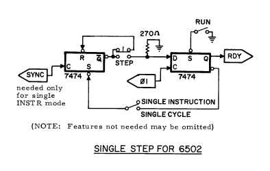
- single step.png (26.32 KiB) Viewed 3505 times
Re: RTC Maxim DS1511Y IRQ woes
Posted: Tue Jun 27, 2017 1:27 pm
by Dr Jefyll
I've attached a small schematics for a single step circuit and I wonder if it will do?
I seem to recognize that as a Wozniak circuit -- someone (Alarm Siren ?) posted it once before. It should work as-is using a 7474, but with any other part you'll need minor changes.
If you use 74LS74 then the 270 ohm resistor may need to be replaced with a somewhat larger value (determined by experiment).
If you use a CMOS flipflop such as 74HC74 or 74HCT74 then replace the 270 ohm with 1K - 4K7 (not critical). On the left FF section add a pullup resistor on the /S input and another on the /R input, and tie the D input (not shown) high. On the right FF section add a pullup resistor to the /S input, and tie the /R input (not shown) high. You can add pullups on both Ck inputs as well, but they're not really needed unless the CPU is NMOS and you use 74HC74 (rather than HC
T).
Woz has taken a slightly dubious short-cut. With 74xx and 74LSxx chips you can kinda-sorta rely on unconnected inputs pulling
themselves high.
I'm assuming that immediately after reset the /IRQ pin is high (although that'd be worth verifying).
For this test it's maybe best to disconnect the RTC's /IRQ output pin from the CPU's /IRQ input pin. You'll need to use two separate pullup resistors.
Re: RTC Maxim DS1511Y IRQ woes
Posted: Tue Jun 27, 2017 6:25 pm
by barrym95838
... Woz has taken a slightly dubious short-cut ...
That's one of his most endearing qualities, IMO.
His hardware and software designs are sprinkled liberally with slightly dubious short-cut seasoning.
Mike B.
Re: RTC Maxim DS1511Y IRQ woes
Posted: Tue Jun 27, 2017 7:45 pm
by Dr Jefyll
I wasn't being critical -- I'm a Woz fan, too! And the "pull themselves high" principle is certainly adequate for unconnected TTL inputs in a hobby environment. You have a very good chance of never getting trouble from using this trick, and it can save you some time and space if you're just hacking around on a breadboard.
But it is a trick for TTL only, and these days it's hard to find any good reason for using TTL. Moreover it's not a trick the datasheets will endorse. In a more cautious design you'd use a pullup or tie the unconnected input high. Otherwise there's a risk of an unwanted signal (noise or leakage current) causing the input -- which in this case you want to be high -- NOT to be high (perhaps only instantaneously).
TTL and CMOS chips both have some degree of noise susceptibility regarding unconnected inputs, but TTL is less critical -- also more predictable, for whatever that's worth. TTL inputs source a small amount of current and thus tend to go high when left unconnected. CMOS inputs have much higher impedance (increasing noise susceptibility if unconnected), and also you can't predict whether they'll drift high or low. So an unconnected TTL input is comparatively safe but still at risk under adverse conditions.
Re: RTC Maxim DS1511Y IRQ woes
Posted: Tue Jun 27, 2017 10:11 pm
by GARTHWILSON
If someone could post a schematic for how to single step the MPU I would be able to do that.
Re: RTC Maxim DS1511Y IRQ woes
Posted: Tue Jun 27, 2017 10:47 pm
by Alarm Siren
someone (Alarm Siren ?) posted it once before.
Did someone call my name?

Yes, it was a Woz circuit that I was never able to get to work properly. I suspect there's something important missing from the diagram that he assumed as "obvious" but isn't.
If someone could post a schematic for how to single step the MPU I would be able to do that.
I have a single-stepping circuit on my current 65c02-SBC, see attachment. It works like a charm and only requires 3 flip-flops (5 if you include debounce, but you could debounce using low-pass filters instead). This is single-instruction stepping, not single-cycle stepping.
You can substitute 5V for 3.3V rail, and you can substitute 74AHC for 74LVC. I wouldn't recommend using 74HC parts due to the propagation delay and assertion of the RDY signal needing to happen within a specific timeframe relative to PHI0. Also note that I've named PHI2 as PHI0 in this diagram, as I find PHI0/PHI2 less confusing than PHI2/PHI2O.
Re: RTC Maxim DS1511Y IRQ woes
Posted: Wed Jun 28, 2017 7:02 pm
by jgroth
If someone could post a schematic for how to single step the MPU I would be able to do that.
That circuit looks a lot simpler. I don't have any Schmidt triggers yet though but I have ordered a couple.
So just want to be sure about a couple of things of what will happen when I single step the MPU.
Suppose my ROM has the reset vector set to $8040 and the vector itself is on address $FFFC
- First press of the button and the low byte ($FC) of the reset address is on the address bus
- Second press and the high byte ($FF) of the reset address is on the address bus
- Third press and the low byte ($40) the of reset routine is on the address bus
- Fourth press and the high byte ($80) of reset routine is on the address bus
Is this the expected behaviour?
Re: RTC Maxim DS1511Y IRQ woes
Posted: Wed Jun 28, 2017 7:46 pm
by GARTHWILSON
RST\ needs to be low for at least two (IIRC) cycles to get all the internals reset. (I'd give it at least a few cycles. It doesn't cost anything.) After RST\ comes up, the reset sequence is 7 cycles long, with 5 of those coming before the vector bytes are fetched. Then the first op code of your reset routine is fetched. The WDC data sheets and programming manual have the cycle-by-cycle behavior of every instruction. You will be able to see the addresses and op codes and so on as you probe at each cycle. It may seem like it will be a hopelessly long process; but in spite of how tedious it is, you will probably figure out the problem in a half hour rather than banging your head against the wall for days or weeks.
Re: RTC Maxim DS1511Y IRQ woes
Posted: Wed Jun 28, 2017 7:50 pm
by BigDumbDinosaur
So just want to be sure about a couple of things of what will happen when I single step the MPU.
Suppose my ROM has the reset vector set to $8040 and the vector itself is on address $FFFC
- First press of the button and the low byte ($FC) of the reset address is on the address bus
- Second press and the high byte ($FF) of the reset address is on the address bus
- Third press and the low byte ($40) the of reset routine is on the address bus
- Fourth press and the high byte ($80) of reset routine is on the address bus
Is this the expected behaviour?
Basically. But...
If you read the 65C02 data sheet you will see this little blurb in it:
- The RESB signal must be held low for at least two clock cycles after VDD reaches operating voltage. Ready (RDY) has no effect while RESB is being held low. All Registers are initialized by software except the Decimal and Interrupt disable mode select bits of the Processor Status Register (P) are initialized by hardware. When a positive edge is detected, there will be a reset sequence lasting seven clock cycles.
Hence the proper way to use the clock single stepper is:
- Press and hold your reset button. You must continuously hold reset during the next step.
- Cycle your clock a minimum of three times. By "cycle," I mean low-high, which follows the way in which the MPU processes. A cycle always finishes with the clock in the high state.
- Release the reset button.
- Cycle the clock six times. On cycle six the address $FFFC should appear on the address bus and the LSB of the reset vector should appear on the data bus.
- Cycle the clock. The address $FFFD should appear on the address bus and the MSB of the reset vector should appear on the data bus.
- Cycle the clock. The address read in steps 4 and 5 should appear on the address bus, and the byte at that address should appear on the data bus. Both RWB and SYNC should be high, indicating the 65C02 is fetching an opcode. Execution is now commencing in your reset handler.
At each step, probe
/IRQ to determine its state. It should be continuously high at all times.
Re: RTC Maxim DS1511Y IRQ woes
Posted: Wed Jun 28, 2017 7:55 pm
by BigEd
For an easy way to see the cycle by cycle behaviour of 6502, see visual6502. For example:
http://visual6502.org/JSSim/expert.html ... ffc&d=1000
Re: RTC Maxim DS1511Y IRQ woes
Posted: Thu Jun 29, 2017 2:08 am
by Michael
If it helps, here's the output I got using a PIC uC for single-cycle stepping an R65C02 several years ago;
Re: RTC Maxim DS1511Y IRQ woes
Posted: Thu Jun 29, 2017 3:51 am
by dwight
With Woz' circuit, if you swap R's and S's as well as Q and Q\, you can
use a pullup resistor on the D input instead of a pull down.
Dwight
Re: RTC Maxim DS1511Y IRQ woes
Posted: Tue Jul 04, 2017 3:51 am
by jgroth
So just want to be sure about a couple of things of what will happen when I single step the MPU.
Suppose my ROM has the reset vector set to $8040 and the vector itself is on address $FFFC
- First press of the button and the low byte ($FC) of the reset address is on the address bus
- Second press and the high byte ($FF) of the reset address is on the address bus
- Third press and the low byte ($40) the of reset routine is on the address bus
- Fourth press and the high byte ($80) of reset routine is on the address bus
Is this the expected behaviour?
Basically. But...
If you read the 65C02 data sheet you will see this little blurb in it:
- The RESB signal must be held low for at least two clock cycles after VDD reaches operating voltage. Ready (RDY) has no effect while RESB is being held low. All Registers are initialized by software except the Decimal and Interrupt disable mode select bits of the Processor Status Register (P) are initialized by hardware. When a positive edge is detected, there will be a reset sequence lasting seven clock cycles.
Hence the proper way to use the clock single stepper is:
- Press and hold your reset button. You must continuously hold reset during the next step.
- Cycle your clock a minimum of three times. By "cycle," I mean low-high, which follows the way in which the MPU processes. A cycle always finishes with the clock in the high state.
- Release the reset button.
- Cycle the clock six times. On cycle six the address $FFFC should appear on the address bus and the LSB of the reset vector should appear on the data bus.
- Cycle the clock. The address $FFFD should appear on the address bus and the MSB of the reset vector should appear on the data bus.
- Cycle the clock. The address read in steps 4 and 5 should appear on the address bus, and the byte at that address should appear on the data bus. Both RWB and SYNC should be high, indicating the 65C02 is fetching an opcode. Execution is now commencing in your reset handler.
At each step, probe
/IRQ to determine its state. It should be continuously high at all times.
Built the single step circuit and followed these step and checked /IRQ if it was high all the time. Well it wasn't. It went low after step 6 but the SEI instruction had then been executed so an interrupt could not happen.
The only thing I could think of after reading the datasheet for n:th time is that IRQF bit in CRA is somehow set. So I read CRA (to reset the FLAG) in the beginning of the initialisation of the RTC (yeah I'm grasping after straws here) to see if that would help. And lo and behold, it worked. So I put back the osc. started the board again and everything works, /IRQ is high from the RTC. I must have by accident caused an interrupt to happen while experimenting and never cleared the flag.
So it was a software problem after all. Oh well, I got a single step circuit now that probably will be handy to have in the future.
Thank you all for your help.