Page 2 of 4
Re: Standardizing an SPI module pinout: SPI-10
Posted: Sun Oct 02, 2016 8:40 pm
by BigEd
Ah, good point!
Re: Standardizing an SPI module pinout: SPI-10
Posted: Sun Oct 02, 2016 9:02 pm
by unclouded
Is it worth considering compatibility with UEXT?
https://en.wikipedia.org/wiki/UEXT
It would be handy to be able to use OTS modules:
https://www.olimex.com/Products/Modules/
They seem to have solved the polarity problem by using keyed connectors:
Re: Standardizing an SPI module pinout: SPI-10
Posted: Sun Oct 02, 2016 10:18 pm
by BigDumbDinosaur
Is it worth considering compatibility with UEXT?
That seems to be a proprietary arrangement, even though it is claimed to be royalty-free. Also, only 3.3 volts is contemplated.
Otherwise, there is nothing special about it, including the standard 10 pin shrouded receptacle, which is used in a lot of varying applications (including JTAG ports).
Re: Standardizing an SPI module pinout: SPI-10
Posted: Sun Oct 02, 2016 10:44 pm
by GARTHWILSON
I've never heard of UEXT until now; but wow, it sure looks nice! And there are already so many modules available for it! I would encourage its use, for situations where its disadvantages are acceptable:
- I has no 5V support.
- It requires an IDC for keying, since AFAIK there are no keyed board-mounted sockets. IDCs are also not as compact. Without the keying, you could still use it, but you'll have to be careful not to plug things in backwards.
- There's no AUX line for SPI devices that may need the extra input like my small graphic LCD uses for a register select. (Most SPI devices have RS built into the instruction bytes, so any RS bits go over the MOSI with other bits.) Either pin 3 or pin 6 could be used to substitute; but then you'll be unable to use either I²C or RS-232/422/485 paralleled on another connector.
- There's no IRQ\ line. Most SPI devices don't need this, but some will.
- There's no RST\ line. Most SPI devices don't need this, but some will.
An adapter could easily be made to plug UEXT devices into an SPI-10 port, or to plug many types of SPI-10 devices into a UEXT port.
I expect to have a lot of work this week, so I was really hoping to get this finalized by tonight; but it doesn't look like we're ready to do that.
Re: Standardizing an SPI module pinout: SPI-10
Posted: Mon Oct 03, 2016 2:43 am
by unclouded
- I has no 5V support.
- It requires an IDC for keying, since AFAIK there are no keyed board-mounted sockets. IDCs are also not as compact. Without the keying, you could still use it, but you'll have to be careful not to plug things in backwards.
- There's no AUX line for SPI devices that may need the extra input like my small graphic LCD uses for a register select. (Most SPI devices have RS built into the instruction bytes, so any RS bits go over the MOSI with other bits.) Either pin 3 or pin 6 could be used to substitute; but then you'll be unable to use either I²C or RS-232/422/485 paralleled on another connector.
- There's no IRQ\ line. Most SPI devices don't need this, but some will.
- There's no RST\ line. Most SPI devices don't need this, but some will.
An adapter could easily be made to plug UEXT devices into an SPI-10 port, or to plug many types of SPI-10 devices into a UEXT port.
Good points. If the pin assignment of SPI-10 is not already set in stone, would it be possible to make SPI-10 partly compatible with UEXT?
Perhaps IRQ\ and RST\ could be pins 5 and 6 because these are open collector for I²C on UEXT so there would be no bus contention between a UEXT host and a SPI-10 device.
Perhaps AUX could be pin 3 (TX, driven by the host ala AUX on a SPI-10 host).
Would these changes result in SPI-only UEXT modules being usable without an adapter on 3V3 SPI-10 hosts or have I overlooked something (likely as I write software mostly)?
Re: Standardizing an SPI module pinout: SPI-10
Posted: Mon Oct 03, 2016 9:01 am
by GARTHWILSON
Good points. If the pin assignment of SPI-10 is not already set in stone, would it be possible to make SPI-10 partly compatible with UEXT?
Below is an effort to do that. See what you think.
Perhaps IRQ\ and RST\ could be pins 5 and 6 because these are open collector for I²C on UEXT so there would be no bus contention between a UEXT host and a SPI-10 device.
In the re-done pinout below, I implemented this, but swapped your 5 and 6 because the I²C clock is not always open-drain, whereas the I²C data definitely is. If the master has a push-pull output on one of these, we want it on RST\, not IRQ\.
Perhaps AUX could be pin 3 (TX, driven by the host ala AUX on a SPI-10 host).
Would these changes result in SPI-only UEXT modules being usable without an adapter on 3V3 SPI-10 hosts or have I overlooked something (likely as I write software mostly)?
So here's the re-done pinout. These are looking into the pins on a 90° header, looking at the controller board from the edge, not down from the top.
First, here's the pinout for an actual UEXT master, showing four of the pins having their functions changed (all within the normal capabilities of the hardware likely to be doing the controlling) to accommodate a 3.3V SPI-10 module:
Code: Select all
      Clk  MISO RST\  AUX  Vdd
     ┌────┬────┬────┬────┬────┐
     │  9 │  7 │  5 │  3 │  1 │
     ├────┼────┼────┼────┼────┤
     │ 10 │  8 │  6 │ (4)│  2 │
═════╧════╧════╧════╧════╧════╧═══(looking into the edge of the board)
      CS\  MOSI IRQ\  NU   Gnd
and then for a 3.3V SPI-10 controller port. It's the same except that pin 4 is actually cut or removed so that a 3.3V SPI-10 module that's keyed only by plugging that hole in the socket cannot be plugged in backwards:
Code: Select all
      Clk  MISO RST\  AUX  Vdd
     ┌────┬────┬────┬────┬────┐
     │  9 │  7 │  5 │  3 │  1 │
     ├────┼────┼────┼────┼────┤
     │ 10 │  8 │  6 │ (4)│  2 │
═════╧════╧════╧════╧════╧════╧═══(looking into the edge of the board)
      CS\  MOSI IRQ\ (cut) Gnd
Now for a 5V SPI-10-only master where you wouldn't want to be able to accidentally plug in a 3.3V-only part into it:
Code: Select all
      Clk  MISO RST\ (cut) Vdd
     ┌────┬────┬────┬────┬────┐
     │  9 │  7 │  5 │ (3)│  1 │
     ├────┼────┼────┼────┼────┤
     │ 10 │  8 │  6 │  4 │  2 │
═════╧════╧════╧════╧════╧════╧═══(looking into the edge of the board)
      CS\  MOSI IRQ\  AUX  Gnd
Again, we're trying to avoid the complexities of voltage translation, especially on the modules, many if not most of which will be very small and simple. Also, we want to use common connectors, and the housings of board-mount sockets with the key on the side are rather rare, unlike those without. I buy long dual-row socket strips and cut off the number of pins I need, which is what I did for the module shown in the head post.
Most shrouded headers are made for IDCs (insulation-displacement connectors, ie, the ones you press onto ribbon cable), so they are longer and have more room on the ends than you would need for a non-IDC socket. I just checked some I have here, and the extra length is not enough to accidentally plug a non-IDC socket in offset by a pin. Hopefully what I checked is representative of all of them on the market.
One minor loss incurred by making SPI-10 mostly compatible with UEXT is that you can no longer shorten a socket to only 6 pins for the tiniest modules, because you need the pins at both ends. That loss is pretty minor if you ask me.
This may not be perfect at accommodating all desirable characteristics, but I think we've made a lot of progress. I may very well be buying some UEXT modules in the future myself. It's sure easier than making them. The only loss I feel is the two 4MB flash modules and a small adapter I've already made, plus the 31 more tiny PCBs (but I had the SO-8 footprint too narrow on those anyway, requiring that the flash ICs' pins be bent under). Not a big loss.
I found there is a keyed board-mount socket too, Omron part number XG4H-1031, Digi-Key stock number Z5647-ND, shown here:
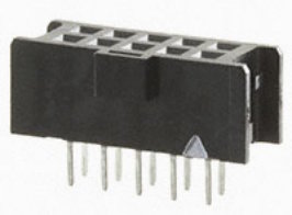
- socket10.jpg (11.15 KiB) Viewed 25413 times
(It's the first keyed one I've found for mounting on a board.) Note the pin-1 marking (the white triangle).
Since the orientation could be a big source of confusion, I'll try to express it a few different ways.
Pin 1 is on the same side with the key, which agrees with my earlier post showing the front edge of the 3U VME board, as well as with all the suppliers' related pictures I could find. So again, the component side of an SPI-10 module has the odd-numbered pins. Make sure you always start numbering from the correct corner for pin header versus socket. (The photo of the board-mount socket above could be turned upside down to match the picture farther down that shows the pin-numbering direction of the IDC with rainbow ribbon cable mounted.) This picture in the UEXT Wikipedia article
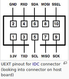
- WikiUEXTpins.jpg (26.02 KiB) Viewed 25413 times
shows the connector upside down if it were a 90° one mounted at the edge of a board. So turn it over, rotating 180°. Again, the odd-numbered pins, and the keyway, will be on top, on the component side of the board.
If you need to connect with a ribbon cable, this picture shows conductor #1 of the ribbons at the left, and the IDC's key in the center. Hopefully it adds more help to get the orientation.
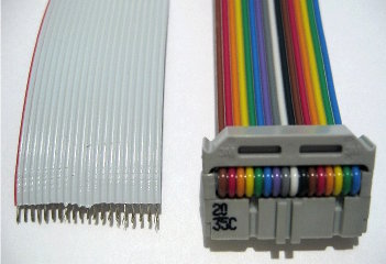
- ribbonInIDC.jpg (22.7 KiB) Viewed 25413 times
I can't believe how much time I've spent on this one little spec. Please check everything for me, and comment. Thanks.
Re: Standardizing an SPI module pinout: SPI-10
Posted: Mon Oct 03, 2016 9:48 am
by BigEd
UEXT is looking like a good standard to build on!
Re: Standardizing an SPI module pinout: SPI-10
Posted: Tue Oct 04, 2016 7:50 pm
by unclouded
Good plan swapping 5 and 6. I didn't know that SCL could be PP.
I like that the proposed SPI-10 key pins are in the RXD and TXD positions of UEXT.
Going through the possibilities:
- SPI-10 module inserted in to UEXT host. Not possible because of the key pin
- UEXT module inserted in to 3V3 SPI-10 host:
- Supported as long as only SPI is in use
- If the UEXT module uses RXD and TXD then nothing bad will happen since RXD is NC and AUX drives TXD, which should be RX on the UEXT module, thus high-impedance. Driving AUX could even be used for (one-way) communications. Driving AUX expecting a different module might cause nothing worse than framing errors on the UEXT module
- If the UEXT module uses I2C then invalid I2C transactions will occur as RST\ and IRQ\ change level. Such transactions should be rejected by the I2C peripheral on the UEXT module
- UEXT module inserted in to 5V SPI-10 host. The magic smoke comes out. This is unavoidable and no different than inserting any other electrically incompatible device in to the port (such as a 10-pin AVR ISP IDC cable with +5V on pin 2). I suspect that most users of SPI-10 check voltages and pin semantics carefully before connecting new hardware
Nice job finding the keyed board-mount socket!
Re: Standardizing an SPI module pinout: SPI-10
Posted: Tue Oct 04, 2016 9:25 pm
by GARTHWILSON
I think that's all correct, except this one (Whew!):
If the UEXT module uses I2C then invalid I2C transactions will occur as RST\ and IRQ\ change level. Such transactions should be rejected by the I2C peripheral on the UEXT module
About the master's I²C clock output being potentially totem-pole (push-pull): I've usually done it that way, and I suspect many other hobbyists have too. It cannot be that way for a multi-master system, nor for allowing a slave to request more time before letting a transaction continue. Multi-master systems are very rare though, and only some slave devices are capable of requesting the pause by holding the clock line low. I don't think any of the I²C parts I've used were capable of it, and just following the timings on the data sheets, I've never overrun a device's ability to keep up. In the case of EEPROMs, when it's programming and needs time, you keep doing the busy poll until you get the ACKnowledge, and then you know you can continue; but while it's not ready, it still lets you keep asking but simply does not pull the data line low during the ACK bit period.
Thanks for the help, unclouded and others. If you see other problems, please comment. I imagine we won't be able to get it 100% compatible but I'd like to make it the best possible and get it finalized.
Re: Standardizing an SPI module pinout: SPI-10
Posted: Tue Oct 25, 2016 1:09 am
by GARTHWILSON
Work has had me very busy for the last few weeks; but there are no rush jobs in sight at the moment, so I'd like to finalize this and lay out some new modules. Any more comments to take into consideration?
Re: Standardizing an SPI module pinout: SPI-10
Posted: Tue Oct 25, 2016 6:52 pm
by cbmeeks
I can't believe how much time I've spent on this one little spec.
Imagine what it took to get SCSI, PCI, etc. into place!!?!?!?
What you're doing is a great thing. My next design will hopefully use SPI devices and I can already see this being a great standard to adopt.
Thanks
Re: Standardizing an SPI module pinout: SPI-10
Posted: Wed Oct 26, 2016 5:20 am
by BigDumbDinosaur
I can't believe how much time I've spent on this one little spec.
Imagine what it took to get SCSI, PCI, etc. into place!!?!?!?
SCSI's ancestor, SASI, was essentially the work of one person. It was only when ANSI got their hands on SASI to standardize it that the time-consumption really got into high gear. Design by committee, anyone?
Re: Standardizing an SPI module pinout: SPI-10
Posted: Wed Oct 26, 2016 5:33 am
by GARTHWILSON
Design by committee, anyone?
Re: Standardizing an SPI module pinout: SPI-10
Posted: Fri Oct 28, 2016 10:29 am
by GARTHWILSON
I'm reminded of the Digilent PMODx2 interface which has 12 posts. For an FPGA the pinout doesn't matter that much, but the power and ground are at one end.
Pin 5,11 and 6,12 are ground and VCC. the other pins are user defined. I believe they have FLASH modules.
http://store.digilentinc.com/pmod-modul ... ing&page=1
http://store.digilentinc.com/by-communi ... tocol/spi/
http://www.digilentinc.com/Pmods/Digile ... cation.pdf
I should have done a web search on Pmod® earlier (especially now that I already placed the order for 200 tiny flash module PCBs with the new pinout since I could get 200 for the same total price as 30). UEXT and Pmod almost make me feel like there was no need for another standard. Is there yet another one that meets all the goals? SPI-10 meets some that UEXT does not. Pmod, like UEXT, already has a lot of modules available for it, but the spec seems much too loose to me, having too many types.
Re: Standardizing an SPI module pinout: SPI-10
Posted: Mon Oct 31, 2016 11:44 pm
by GARTHWILSON
SPI-10, a hobbyist-friendly connector standard, for small SPI modules
This post is to summarize what we settled on in in previous posts regarding the SPI-10 specification, background, and goals. My thanks go to those who contributed above.
Background
SPI is is a four-wire, synchronous-serial interface standard used by hundreds, possibly thousands, of different ICs on the market. The small number of wires reduces layout or assembly time as well as board space, compared to parallel interfaces. All wires are unidirectional, so voltage translation (if necessary) is easy. Possible speeds range from zero to nearly 200Mbps, and gone are the timing requirements of asynchronous serial interfaces like RS-232 (now officially called TIA-232). SPI is trivial to bit-bang with standard I/O ICs used in 65xx computers, or you can use dedicated SPI hardware like Daryl's 65SPI IC or a microcontroller or programmable logic.
However, SPI does not specify a connector. In most situations, there's no need to, assuming the SPI parts are on the same board with the controller and don't go through any connectors, or if they do, the connector might be handling other signals too. In our case, we want to be able to make small modules that plug in, similar to the SD-card idea, and make it easier to share designs and perhaps even hardware in the future, with a connector that's hobbyist-friendly.
Filling a different SPI need, there's our super-flexible 65SIB (6502.org serial interface bus, not to be confused with Daryl's 65SPI IC). 65SIB, which can be as simple or as intelligent as you want it to be, was developed to extend the usefulness of SPI and similar interfaces in several directions at once. 65SIB however, with its 20-pin connectors, ribbon cables, auto addressing, and other features, is intended for connecting multiple pieces of outboard equipment, similar to the IEEE-488 idea, and still leaves a need for something smaller like SPI-10.
Imagine small, plug-in modules for:
- flash memory
- an IR port
- a real-time clock (ie, time-of-day clock, including alarm interrupt output)
- temperature sensor
- ambient light sensor
- SD card
- wireless RF transceiver
etc., all small enough to be mechanically supported by a 2x5 pin header connector that 0.5" long and 0.2" wide. If a cable connecting other things outside the module is acceptable, we can add a lot more to the list:
- analog-to-digital (A/D) converters
- digital-to-analog (D/A)
- keypad
- display
- stepper-motor controller
- servo
- general-purpose I/O
and more. A single-board computer's SPI-10 port can be used to interface all of these (one at a time), and multiple ports could be put on the same SBC.
Goals and characteristics
- Uses common, hobbyist-friendly connectors which go into common perfboard with holes on .100" centers. The pins are .025" square posts.
- capability for 5V devices and lower-voltage devices too such as 3.3V (although one port will usually only work at one voltage)
- keyed, so you cannot plug the module in backwards, or plug a 3.3V (or lower) module into a 5V port
- partial compatibility with UEXT, although SPI-10 will also have attractions UEXT does not. UEXT devices that only use the SPI portion of the UEXT spec can plug into 3.3V SPI-10 ports and operate.
- has one SPI channel (data in, data out, clock, and one select), plus 3 more pins which the slave can optionally use: IRQ\ slave output, RST\ slave input, and an auxiliary function pin (normally an input to the slave)
- The socket goes on the module, since the module will get more handling than the controller board, and pins present more risk of mechanical or static damage. The controller gets the pin header.
- Power is available on the connector, whether 5V or 3.3V.
- Shrouded, keyed pin headers are preferred but not required. If there's a shroud, the keyway in the shroud is necessary for plugging in UEXT devices. Matching PCB-mount sockets are available (Omron part number XG4H-1031, Digi-Key stock number Z5647-ND, shown in a post above) but the main method of keying for SPI-10 modules is pin 3 or 4 of the pin header cut (for 5V or 3.3V respectively) and the corresponding socket hole blocked.
- SPI-10 is not intended to be hot-pluggable, because common, hobbyist-friendly connectors do not give any way to connect the power and ground first when plugging in and disconnect them last when unplugging. However, if necessary, the controller board can bring its output signals low and turn off the power to the SPI-10 port for the purpose of plugging in or unplugging a module without powering down the entire controller board. An LED on the controller board, showing the power-on status of the port, would be good. Modern LEDs only need 1 or 2mA for the job.
Pinout
First, these are the pins needed. They are not in order of pin number. The terms "master" and "controller" are interchangeable. The SPI-10 module is the slave.
- SS\ (slave-select-not module input. The controller brings this low to select the module for SPI transactions. This is the only line that should not be bused with other SPI-10 ports or other SPI ICs.)
- Clock (The controller uses this line to coordinate bit transfers by telling the slave when to sample the MOSI state and when to go to the next MISO bit.)
- MOSI (master-out, slave-in data line)
- MISO (master-in, slave-out data line)
- RST\ (most SPI ICs don't need this, but a few will. Master controls it.)
- IRQ\ (a few SPI ICs will have this IRQ\ open-drain/collector output) Note: "IRQ\" does not necessarily mean it connects directly to your 6502/816's IRQ\ pin. One user asked if it would be ok to connect it to a VIA's CB1 pin. The answer is "Sure, just put a pull-up resistor on it." IRQ\ is common nomenclature for this kind of thing.
- AUX (auxiliary line, whose function will vary among the minority of SPI ICs that use it. Master controls it.)
- Ground
- Power to the module, typically 5V or 3.3V
- (plus one for keying)
Here's the pinout for a 3.3V SPI-10 controller port, looking into the pins. Pin 4 is actually cut or removed so that a 3.3V SPI-10 module that's keyed only by plugging that hole in the socket (as opposed to having a key on the outside of the socket) cannot be plugged in backwards.
- textPinout3V3.gif (9.81 KiB) Viewed 25213 times
An SPI-10 module with hole #4 plugged would not be able to plug into a UEXT controller.
Now for a 5V SPI-10-only port where you wouldn't want to be able to accidentally plug a 3.3V-only part into it:
- textPinout5V.gif (9.69 KiB) Viewed 25213 times
and again a module with hole #3 plugged would not be able to plug into a UEXT controller (where it wouldn't work anyway). 5V versus 3.3V ports have different pins cut (#3 versus #4, respectively). There is probably no danger of damaging anything by plugging a 5V module into a 3.3V port; but the vice-versa is not true.
SS\ above stands for "slave-select not." You might also see CS\ for "chip-select not," and individual ICs may have a pin called CE\ for "chip-enable not." (My apologies—I don't think there's any way to do the overbar in forum posts.)
Pin 1 is on the same side with the keyway in the optional shroud, agreeing with an earlier post showing the front edge of the 3U VME board, as well as with all the suppliers' related pictures I could find. The component side of an SPI-10 module has the odd-numbered pins, and this keyway. If the controller board has a 90° pin header at the edge of the board, the components on the controller board and the module will face the same way. Make sure you always start numbering from the correct corner for pin header versus socket. 90° sockets for the module (as opposed to IDCs), especially sockets with the key on the outside, seem to be rare; and it takes less board space anyway to use straight soldertail pins on the socket, putting the PCB between the soldertails and soldering the row of odd numbers to pads on the component side, and the row of even numbers to pads on the opposite side.
If you opt for a 90° shrouded, keyed header (which goes on the controller, not the module), it will look something like this (except that you'll remove one of the pins, either #3 or #4):
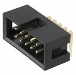
- shrouded10b.jpg (13.68 KiB) Viewed 25213 times
Two practical header orientations for the controller board are the lower two in this picture (thanks to Dr Jefyll for the next three pictures):
Take care to number the pins correctly. Pin 1 is indicated here with the arrow. Pin 2 is below it.
The pinout, shown photographically for a vertical, unshrouded pin header, is as follows:
Headers and sockets both can be purchased in longer strips, up to 100 positions, and you can cut off however many you need to use at a time. This may come out cheaper; and if you unexpectedly need different lengths for other projects, you have stock.
My own first SPI-10 module is a flash-memory module, shown two posts down. I've built a few up for my own use, and will be supplying at least the tiny boards for others who would like them.