somewhere on the net I saw a bootup scheme for Z80 in which the host computer connected only to the Z80 clock and interrupt lines. (And reset, I guess, but still it was downright astonishing.) The gist of it was to stick the bytes in memory using the stack pointer as it responds to interrupts.
It's amazing that such a small number of control lines would be sufficient for booting. I tried to adapt this idea for 65xx CPU's, but timing is critical and interrupt latency is somewhat variable. I ended up with serious doubts that my plan could be made to work. (I posted about that
here. The original Z80 version is
here. Also the OP proposed a 5-wire version
here.)
Now I'm happy to report an alternative plan, one which doesn't involve interrupts. This all but eliminates latency issues, making timing
much easier to manage. And, hardware-wise, there's no longer any need for a connection to the NMI pin.
Here's the TLDR: under control of a bootup microcontroller or a remote host computer,
we force NOP's to run the 65xx Program Counter around to specific 16-bit values; then we force a JSR to push each 16-bit value to stack. Eventually the stack contains a program we can execute. (The program may be another loader, one that's not limited to writing in the stack area.) A detailed description follows. The main challenge is that S begins in an uninitialized state, which means we don't know exactly where our code will get written to.
Edit: Since I first posted this idea I have made some refinements. I'll post those too if there's any interest.
Edit: for
a working version that's faster and simpler, see my 2018 thread
Ultra-minimal 3-wire Interface boots up 65xx CPU's
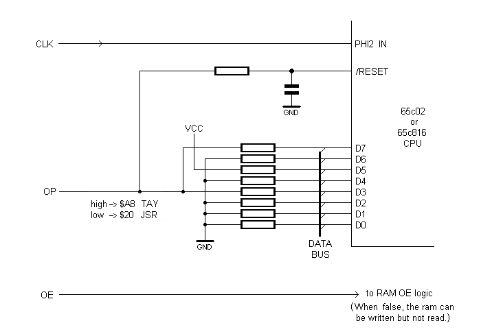
- bootload detail.png (6.48 KiB) Viewed 6731 times
As you see, the three lines from the host system are called CLK, OP and OE. OE controls RAM output enable, and may be active-high or active-low according to whatever suits your circuit. OP determines what
OPCODE will appear on the data bus when it's floating and the pullup/pulldown resistors are doing their thing.
To put $20 on the bus, pull OP low. $20 is the opcode for JSR, a 3-byte, 6-cycle instruction.
To put $A8 on the bus, set OP high. $A8 is the opcode for TAY, a 1-byte, 2-cycle instruction. TAY is used as a kind of NOP.
OP also feeds an RC filter that drives /RESET. For that reason OP is kept high by default, brought low only for brief intervals (a few microseconds, perhaps). The exception is the case when a reset is desired. Then OP is held low for a much longer period (eg: 1 ms).
Here's a walkthrough of the boot sequence.
- After powerup, hold OP low long enough (1 ms or more, depending on the R and C) to ensure the CPU /RESET pin is also low. Using CLK we feed the CPU maybe 8 or 10 wakeup clock pulses, then stop. Next we bring OP high and wait 1 ms for /RESET to follow suit.
- Set OE false so the resistors have control of the data bus
- Put $20 on the bus (by pulling OP low). Deliver 7 clocks to execute the reset sequence. The PC = $2020 at this point.
Our first goal is to
get a known value into S (the stack pointer). To do that we load and run a position-independent program.
We repeat the following sequence 64 times:
- Put $A8 on the bus. Issue enough clocks to make PC= $EA9A-2. We're about to do a JSR. The address of the 3rd byte of the JSR instruction will get pushed.
- Put $20 on the bus. Issue 6 clocks. (PC = $2020, and $EA9A got pushed.)
- Put $A8 on the bus. Issue enough clocks to make PC= $EAA2-2. We're about to do a JSR. Again the address of the 3rd JSR instruction byte will get pushed.
- Put $20 on the bus. Issue 6 clocks. (PC = $2020, and $EAA2 got pushed.)
Page $01 is now full of repetitions of the following program (256 bytes total):
Code: Select all
A2  EA    LDX# $EA     ;load X with the value $EA (even though we'd prefer $FF)
9A        TXS          ;transfer X to S
EA        NOP          ;the NOP is just padding. (It's easier if we deal with even numbers of bytes.)
                       ;
A2  EA    LDX# $EA     ; again
9A        TXS
EA        NOP
                       ; and so on
To proceed, we:
- Put $A8 on the bus. Issue enough clocks to make PC= $0100
- Set OE true so the RAM can be read
- issue 12 clocks -- enough to run the three-instruction sequence twice.
Now we know S = $EA. The strange procedure is necessary because S was initially unknown, and when we wrote the 256 bytes to Page 1 we began at an unknown location. So, when we later began execution at $0100 it's possible the first thing we did was to execute the LDX
operand as if it were an opcode! That's why the operand is chosen to coincide with a harmless, one-byte opcode ($EA). And that's why we issue enough clocks to run
two iterations of the sequence. If things get off on the wrong foot then the first iteration won't initialize S as desired.
Moving on: Presumably we have a more conventional program prepared -- the code which it's actually our goal to run.

As before, we'll push the code to RAM two bytes at a time. That means a pad byte will be needed if the program length isn't already an even number.
- Set OE false so the resistors can take control again
- Put $20 on the bus. Issue 6 clocks. PC= $2020. (NB: S= $E8. S's initial setting immediately got reduced by 2)
- Put $A8 on the bus. Issue clocks until PC= n-2. We're about to do a JSR. n -- the last 2 bytes of the program -- will get pushed
- Put $20 on the bus. Issue 6 clocks. PC = $2020.
- Put $A8 on the bus. Issue clocks until PC= n-2. We're about to do a JSR. n -- the next-to-last 2 bytes of the program -- will get pushed
- Put $20 on the bus. Issue 6 clocks. PC = $2020
- [ ... ]
- Put $A8 on the bus. Issue clocks until PC= n-2 We're about to do a JSR. n -- the first 2 bytes of the program -- will get pushed
- Put $20 on the bus. Issue 6 clocks. PC = $2020
Now the program is in place. All that remains is to run it:
- Put $A8 on the bus. Issue clocks until PC= the address of the first byte of program
- Set OE true so the RAM can be read
- issue enough clocks to run the program!

Footnote 1: one limitation (aside from speed) is that the initial setting of S -- $EA -- is lower than might be desired. A lower initial setting reduces the maximum program size. If that's a problem you can choose a different harmless, one-byte opcode as the operand for LDX. $FA (PLX) is acceptable. Or, choose $08 (PHP) and pad the end of your program so it exceeds 256 bytes and wraps you around.
Footnote 2: Obviously this bootup method needs to run a
lot of TAY instructions to increment PC as required. That's slow. But, FWIW, a slight increase in complexity can cut the number of TAY's approximately in half. Anytime you're about to...
- Put $20 on the bus. Issue 6 clocks. PC= $2020
- Put $A8 on the bus. Issue clocks until PC= [whatever]
...you may, if it helps (this requires checking on a per-case basis), do the following instead:
- Put $20 on the bus. Issue 1 clock. Put $A8 on the bus. Issue 5 clocks. PC= $A8A8
- Issue clocks until PC= [whatever]
Footnote 3:So far the idea hasn't been tested, and I'm concerned that perhaps /RESET itself exhibits variable latency. Although 65xx datasheets perhaps tacitly
imply there's a consistent number of clocks between /RESET going high and the fetch of the first instruction, there may in fact be some variability. This isn't something we can expect the datasheets to mention, as it's a detail that (almost) nobody cares about.
-- Jeff